
Double-auto-collimation optical system checking and regulating tube

An optical system and self-collimation technology, applied in the direction of optics, optical components, instruments, etc., can solve the problems of coverage pitch deviation, high cost, very strict environmental requirements, etc., to ensure stability and reliability, and eliminate external structural deformation , high stability and high precision

Active Publication Date: 2015-04-29
NO 63908 TROOPS PLA
View PDF8 Cites 0 Cited by
  • Summary
  • Abstract
  • Description
  • Claims
  • Application Information

AI Technical Summary

Problems solved by technology

At present, all measurement methods and methods are verified by multi-collimator technology. This technology cannot completely cover equipment and parameters, and requires repeated erection and repeated leveling. The repeatability, reliability and consistency cannot be guaranteed. The measurement equipment is very It is huge, expensive, and has very strict environmental requirements. It can only be built in a laboratory in a special environment, and cannot meet the measurement requirements of the aiming equipment.
[0003] The design of conventional inspection and adjustment tubes must meet one condition: the focal length of the inspection and adjustment tube is more than 2 to 3 times the focal length of the tested collimator. The miniaturization and reliability design of the tube have brought great problems, which cannot meet the needs of the implementation of measurement guarantee; in addition, ordinary inspection and adjustment tubes do not have the function of micrometer measurement, and cannot realize the verification of "reticle overlap". It needs to be equipped with additional equipment such as T3000A or T5100A. This equipment is as high as hundreds of thousands, and the verification cost is extremely high
The inspection and adjustment tube designed with a single optical path cannot provide quantitative angle measurement and reading functions, cannot realize the verification of the zero position error of the azimuth and zero calibration light pipes, and cannot cover the verification of the pitch deviation in the case of one leveling and one erection
[0004] In the traditional aiming equipment verification device, the aiming target group adopts a distributed installation method, that is, multiple collimators are installed on the same bracket through their respective fixing parts, which may easily cause changes in the technical parameters and relative positions of the aiming target group. Moreover, the requirements for the operating environment temperature are very strict, which cannot meet the accompanying measurement guarantee work.

Method used


Image

  • Double-auto-collimation optical system checking and regulating tube
  • Double-auto-collimation optical system checking and regulating tube
  • Double-auto-collimation optical system checking and regulating tube

Examples


Embodiment Construction

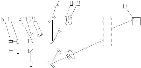
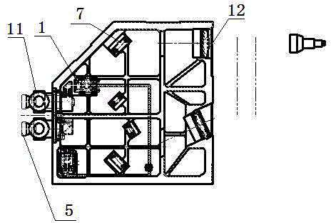
[0016] Such as figure 1 As shown, a double self-collimating optical system inspection tube includes a casing, and two self-collimating optical systems are arranged in the casing. The first self-collimation optical system and the second self-collimation optical system irradiate the light emitted by the light source onto the measured mirror 10 through the optical device respectively, and the first self-collimation optical system and the second self-collimation optical system The included angle formed by the two light rays emitted by the optical system is an acute angle, and the measured reflector 10 is located at the intersection of the two rays. If the reflective surface of the measured reflector is perpendicular to the incident light of the optical system, the light is still Backtrack.

[0017] Each self-collimating optical system includes a light source 1, a cross reticle 2, a first dichroic prism 4, a first mirror 6, a second mirror 7, a first objective lens 8, a second obj...


PUM


Abstract

The invention discloses a double-auto-collimation optical system checking and regulating tube which relates to the technical field of measuring devices which are characterized by adopting an optical method. The tube comprises a shell, wherein two auto-collimation optical systems are arranged in the shell; a first auto-collimation optical system and a second auto-collimation optical system respectively irradiate light which is emitted from a light source onto a measured reflective mirror through optical devices; and an included angle which is formed by two light rays emitted by the first auto-collimation optical system and the second auto-collimation optical system is an acute angle. The checking and regulating tube adopts a light splitting principle and two groups of light splitting prisms; antireflection films are formed on incident and emergent surfaces through vacuum laser so as to make up the light energy loss which is caused by light splitting; a light splitting film is coated on a gluing layer, the thickness of the film is controlled so as to enable the light splitting ratio to reach 1:1; one light path provides high-precision auto-collimation to a target, so that the target is enabled to be clear and stable, and a problem of cross reticle superposition verification is solved; and the other light path provides a reading micrometer function so as to solve a zero position error verification problem.

Description

technical field [0001] The invention relates to the technical field of measuring devices characterized by adopting optical methods, in particular to an integrated processing device with double self-collimating optical systems. Background technique [0002] Aiming equipment generally includes theodolite, azimuth, zero calibration light tube, electrical benchmarking instrument, magnetic level and other equipment. Whether the technical indicators are normal or not is directly related to the accuracy of missile hits, and regular metrological verification or calibration is required. At present, all measurement methods and methods are verified by multi-collimator technology. This technology cannot completely cover equipment and parameters, and requires repeated erection and repeated leveling. The repeatability, reliability and consistency cannot be guaranteed. The measurement equipment is very Huge, expensive, and very strict on the environment, it can only be built in a laborator...

Claims


Application Information

Patent Timeline
Patent Type & Authority Patents(China)
IPC IPC(8): G02B27/30
Inventor 雷正伟刘福冯广斌华翔牛满科张军王胜磊耿斌刘海涛贾波
Owner NO 63908 TROOPS PLA
Learn More