
Microwave radiometer wave detector and wave detection method thereof based on integrated multiplier

A microwave radiometer and multiplier technology, applied in the field of microwave remote sensing, can solve the problems of small dynamic range, limited detection linearity, measurement accuracy, detection voltage temperature drift, etc., to reduce circuit complexity, improve detection linearity, excellent The effect of linearity

Inactive Publication Date: 2013-07-24
XIAN INSTITUE OF SPACE RADIO TECH
View PDF3 Cites 2 Cited by
  • Summary
  • Abstract
  • Description
  • Claims
  • Application Information

AI Technical Summary

Problems solved by technology

In view of the demand for power detection of microwave radiometers, the most commonly used method is diode square-law detection, which uses diode nonlinearity, that is, the square-law region for power detection. However, because diodes have two inherent characteristics: (1) Its nonlinear region Narrow means that the dynamic range of the square-law detector is small. Usually, the input power of the square-law detector is below -30dBm, and the signal after detection is also very weak; (2) The volt-ampere characteristic changes with temperature. The antenna receives the microwave radiation brightness temperature changes from the observation scene, so it is necessary to solve the problem of small detection dynamic range and temperature drift
Because the output change caused by the temperature drift of the detector will be mistaken for a change in the apparent temperature input of the antenna, which will cause measurement errors. Temperature drift is an important factor that limits the linearity and measurement accuracy of the detector.
In order to solve the problem of detection voltage temperature drift and improve the dynamic range of detection to achieve high linearity and high sensitivity of microwave radiometer measurement, the measures taken in the past increased the complexity of the circuit

Method used


Image

  • Microwave radiometer wave detector and wave detection method thereof based on integrated multiplier
  • Microwave radiometer wave detector and wave detection method thereof based on integrated multiplier
  • Microwave radiometer wave detector and wave detection method thereof based on integrated multiplier

Examples


Embodiment Construction

[0014] Below in conjunction with accompanying drawing and specific embodiment the present invention will be described in further detail:

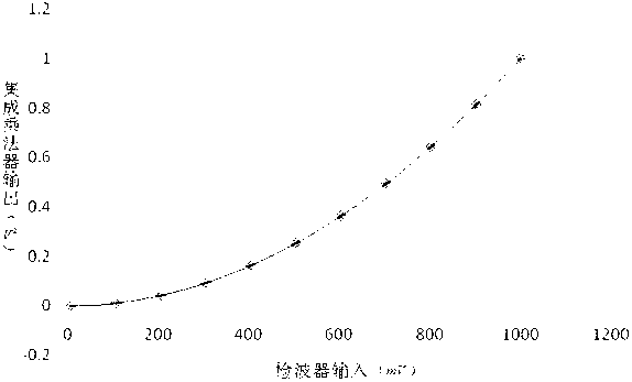
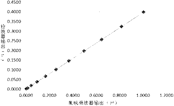
[0015] like figure 1 The method described in the present invention shown is the part in the dotted box in the figure, which is a functional block diagram of a microwave radiometer detector and its detection method based on an integrated multiplier of the present invention, including an integrated multiplier, a low-pass filter, and a DC amplifier . The input power of the microwave radiometer is formed by thermal noise. The signal received by the microwave radiometer antenna enters the detector after frequency conversion, amplification, and filtering. The intermediate frequency signal input by the detector obeys a Gaussian distribution with a mean value of 0 and a variance of σ. The power of the signal, given as a voltage. The working frequency band of the integrated multiplier meets the frequency range of the intermediate frequency signal ...


PUM


Abstract

The invention relates to a microwave radiometer wave detector based on an integrated multiplier and a wave detection method thereof. The traditional method using a non-linear area of a diode is replaced to realize the same function. The wave detection method has the advantages that the integrated multiplier has a very large dynamic range, and the temperature drift is very little, so an additional circuit is not needed to adjust the outputted dynamic range and the temperature characteristic of a receiver, and the circuit complexity caused by the diode is greatly reduced; the integrated multiplier is different from the diode, the wave detection output results are kept consistent within the very large temperature range, and the requirement on the working temperature range of a microwave radiometer is also reduced; compared with a microwave diode wave detector, the integrated multiplier usually has higher linearity within the very large temperature range, so that compared with the diode wave detection method, the wave detection linearity is also improved; and the implementing is simple, the reliability is high, and the microwave radiometer wave detector and the wave detection method are suitable for all satellite-borne microwave radiometer wave detection applications, and have broad market application prospect.

Description

technical field [0001] The invention belongs to the technical field of microwave remote sensing, and relates to a microwave radiometer detector based on an integrated multiplier and a detector method thereof. Background technique [0002] The microwave radiometer is a passive microwave remote sensing device, which detects the characteristics of the target by receiving the microwave energy radiated from the observed scene. The input power of the microwave radiometer is formed by thermal noise. The signal received by the antenna of the microwave radiometer enters the detector after frequency conversion, amplification and filtering. Get the power of the signal, given as a voltage. After the output voltage of the detector is calibrated, the relationship between the output voltage and the apparent temperature of the antenna can be established, and the brightness temperature of the observed object can be determined. The temperature value contains some important physical informati...

Claims


Application Information

Patent Timeline
IPC IPC(8): G01S1/04
Inventor 周晓华李军李浩迟吉东陈文新段崇棣李延明
Owner XIAN INSTITUE OF SPACE RADIO TECH
Learn More