
display device

A technology for display devices and display devices, which is applied in the directions of identification devices, optics, instruments, etc., and can solve problems such as affecting display effects and reducing the visibility of OLED devices

Active Publication Date: 2016-08-31
BOE TECH GRP CO LTD
View PDF5 Cites 0 Cited by
  • Summary
  • Abstract
  • Description
  • Claims
  • Application Information

AI Technical Summary

Problems solved by technology

However, when the external light is relatively strong, the display device also has a better mirror function, which seriously affects the normal display effect
[0007] The above method can function as a mirror when the OLED device does not emit any light, that is, it can function as a mirror when the OLED device is not displaying, but when the OLED is performing display operations, especially in a strong external light environment, it is greatly reduced. Improve the visibility of the OLED device itself

Method used


Image

  • display device
  • display device
  • display device

Examples


Embodiment Construction

[0028] The specific implementation manners of the present invention will be further described in detail below in conjunction with the accompanying drawings and embodiments. The following examples are used to illustrate the present invention, but are not intended to limit the scope of the present invention.

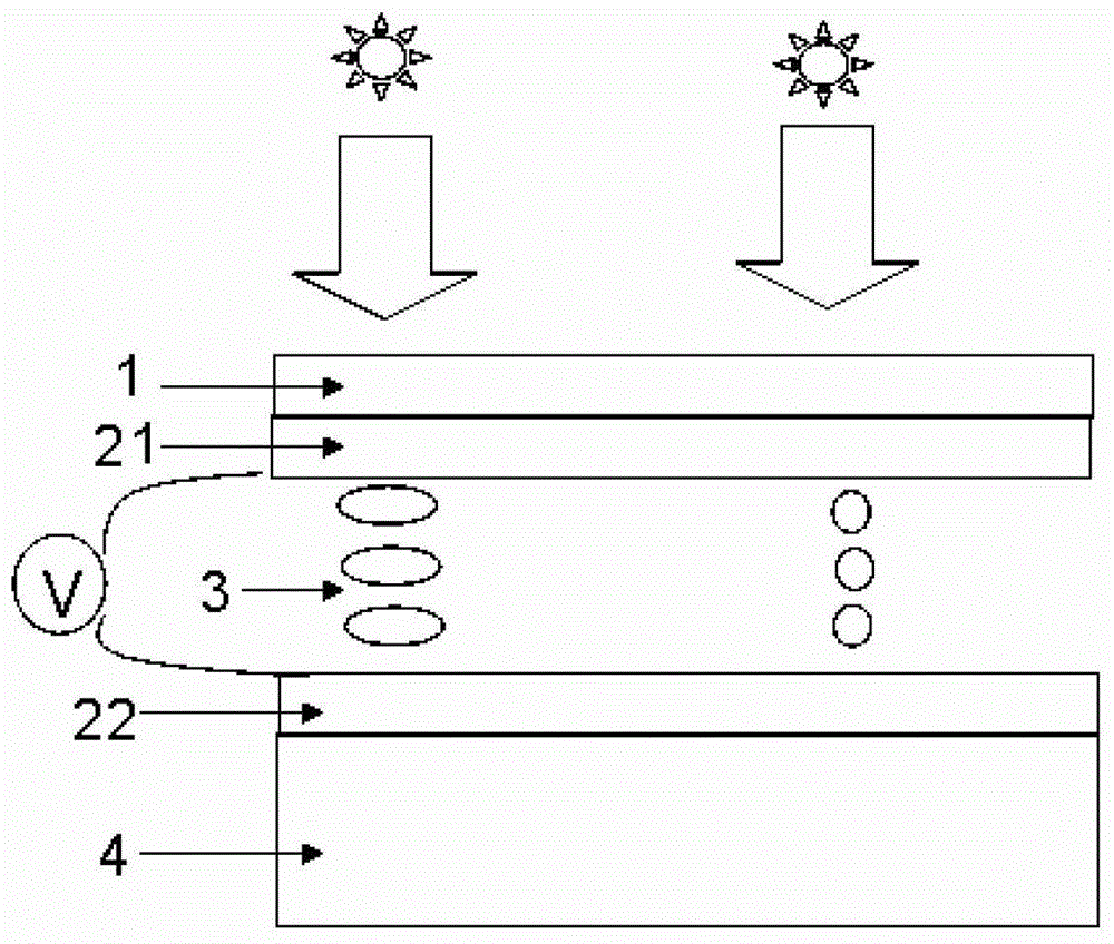
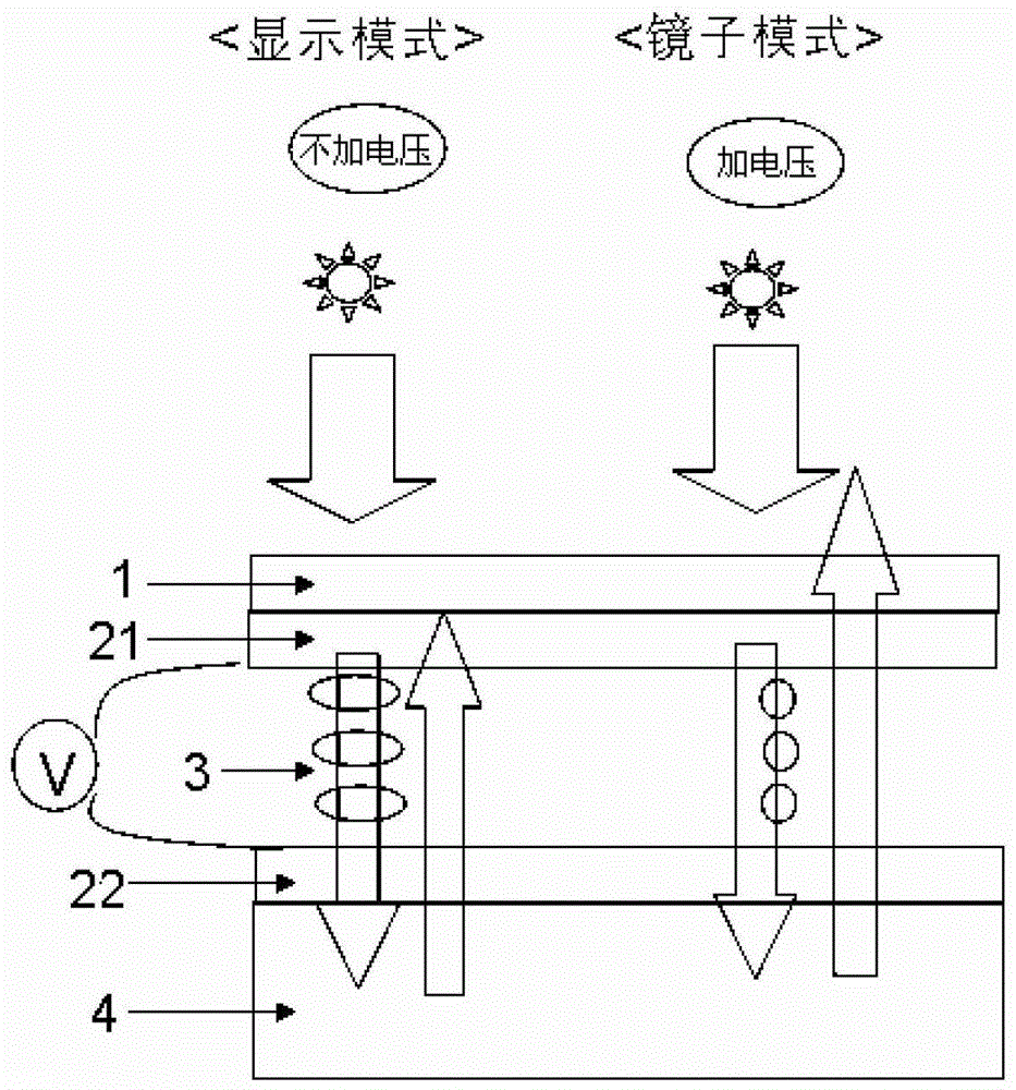
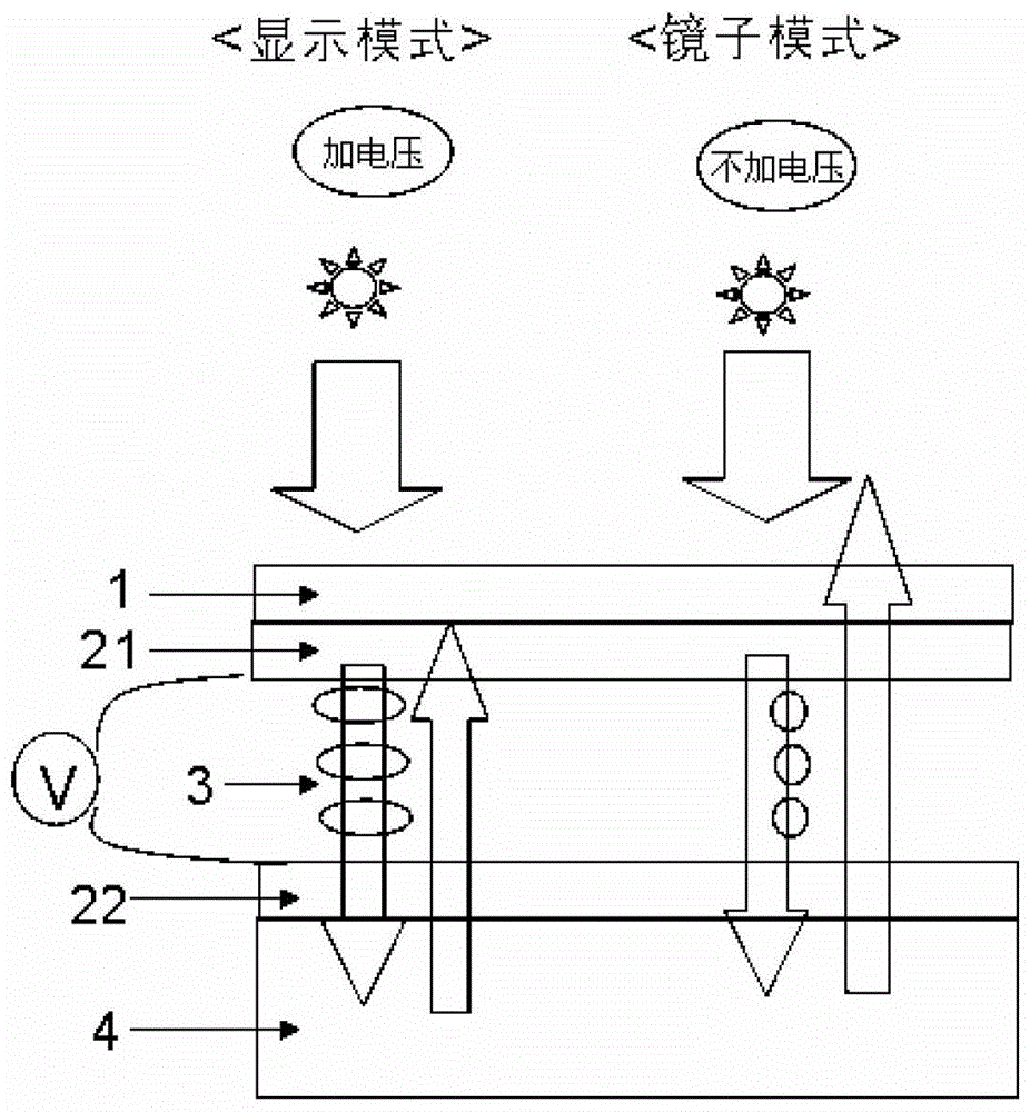
[0029] figure 1 It is a structural schematic diagram of the device of the present invention. The present invention provides an organic light emitting diode display device, which comprises: an organic light emitting diode display device 4 , a liquid crystal layer and a polarizer 1 sequentially located on the organic light emitting diode display device 4 . In this embodiment, the liquid crystal layer includes: a first substrate 21 , a second substrate 22 and liquid crystal molecules 3 filled therebetween. Alignment layers are sequentially provided on the facing surfaces of the first substrate 21 and the second substrate 22 . At least one of the first substrate 21 and the s...


PUM


Abstract

The invention discloses an organic light emitting diode display device and relates to the technical field of liquid crystal display. The display device includes: an organic light emitting diode display device and a polarizer located above the organic light emitting diode display device, and also includes a liquid crystal layer located between the organic light emitting diode display device and the polarizer, and the liquid crystal layer in the liquid crystal layer The direction of the slow axis of the polarizer forms a predetermined angle with the direction of the absorption axis of the polarizer, so that when the organic light emitting diode display device is in a non-display state, the light is incident on the outside of the organic light emitting diode display device from the polarizer The light is reflected by the organic light emitting diode display device and then exits from the polarizer. The present invention uses the liquid crystal layer to realize the function of the λ / 4 film, and adds the mirror function with clear reflection characteristics to the OLED display device, so that the OLED display device can be used as a clear mirror when it is not performing display operations.

Description

technical field [0001] The present invention relates to the field of display technology, in particular to a display device. Background technique [0002] In recent years, in order to meet the diverse needs of customers, businesses are promoting the compounding and multi-functionalization of electronic products. Correspondingly, the field of organic light emitting diode (Organic Light Emitting Diode, OLED) display devices is also researching and developing new products that not only have inherent display functions but also include other functions. As part of the multifunctionalization of such products, people are trying to add mirror functions to OLED display devices such as mobile phones or Personal Digital Assistants (PDAs). [0003] In the prior art, by depositing metal powders such as silver powder and titanium powder in the vacuum part of the OLED device, a reflective window or a bonded reflective film is formed separately to form a mirror, or mixed in the electron inje...

Claims


Application Information

Patent Timeline
Patent Type & Authority Patents(China)
IPC IPC(8): G02F1/1333G09F9/33
CPCG02F2201/44H10K59/50H10K59/878
Inventor 金起满郑喆奎柳在健
Owner BOE TECH GRP CO LTD
Learn More