Method for preparing SE (Selective Emitter) solar cell by utilizing sectional type mask graph

A mask pattern, segmented technology, applied in the manufacture of circuits, electrical components, final products, etc., can solve the problems of high cost and large consumption of SE etching mask slurry

Inactive Publication Date: 2013-07-24
TIANWEI NEW ENERGY HLDG
View PDF4 Cites 7 Cited by
  • Summary
  • Abstract
  • Description
  • Claims
  • Application Information

AI Technical Summary

Problems solved by technology

[0021] In order to overcome the technical defects of large consumption of SE etching mask slurry and high cost in the traditional

Method used


Image

  • Method for preparing SE (Selective Emitter) solar cell by utilizing sectional type mask graph
  • Method for preparing SE (Selective Emitter) solar cell by utilizing sectional type mask graph
  • Method for preparing SE (Selective Emitter) solar cell by utilizing sectional type mask graph

Examples


Embodiment 1

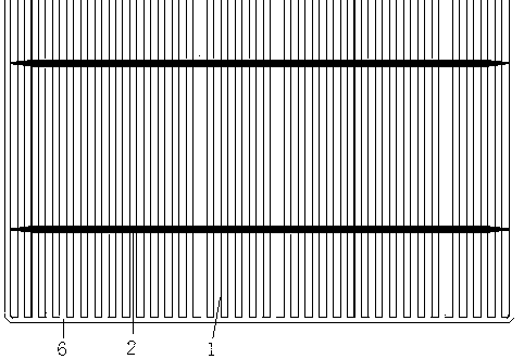
[0056] Such as figure 2 , The thin grid line 1 is divided into segmented thin grid lines composed of a:b=1:1 by the straight-through type, and each segmented SE mask coating area adopts a rectangular shape, and the segmented SE mask coating covers The distribution between the regions can be arranged in a regular hexagon, so that the electrons in all the emission regions can be in the shortest distance, that is, within the radius of the equal diameter circle centered on the center of the segmented SE mask coating area. Each segment of SE mask paint is collected by the thin grid electrode connected to the covered area. This solution can reduce the slurry consumption of the SE etching mask fine grid line by 50% while ensuring the conversion efficiency.

Embodiment 2

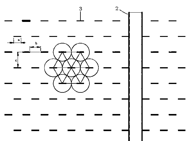
[0058] Such as image 3 , The thin grid line is divided into a segmented SE mask coating area composed of a:b=1:6.26 by a straight-through type, each segment adopts a circular shape, and the distribution between the segmented SE mask coating area can be The regular hexagonal arrangement is adopted so that the electrons in all the emission areas can be divided by each segment within the shortest distance, that is, within the radius of the equal diameter circle centered on the center of the segmented SE mask coating area. Collected by wire electrodes. This solution can reduce 86.2% of the SE etching mask fine grid line slurry consumption while ensuring the conversion efficiency.

Embodiment 3

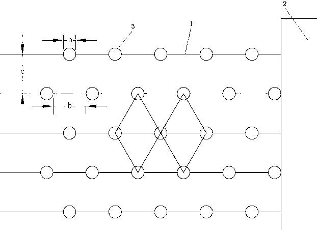
[0060] Such as Figure 4 , The thin grid line SE mask paste pattern is divided into a segmented SE mask coating coverage area composed of a:b=3:1 by a straight-through type, each segment adopts a bamboo shape, segmented SE mask coating The distribution between the coverage areas can be arranged in a regular hexagon, so that the electrons in all the emission areas can be divided by each segment within the shortest distance, that is, within the radius of the equal diameter circle centered on the center of the thin grid line. The SE mask paint is collected by the thin grid electrode connected to the covered area. This solution can reduce the slurry consumption of the SE etching mask fine grid line by 33.3% while ensuring the conversion efficiency.

[0061] In the above embodiments, a is the length of the segmented SE mask coating area, and b is the distance between the two adjacent segments of the segmented SE mask coating area. It can be seen that the SE slurry saving effect of Exa...


PUM


Abstract

The invention discloses a method for preparing an SE (Selective Emitter) solar cell by utilizing a sectional type mask graph. The method comprises the step of forming an SE mask graph on a diffusing surface by utilizing an SE etching mask sizing agent, wherein the part, which corresponds to a thin grid line, of an SE mask is in a sectional type discontinuous shape, thus forming a sectional type SE mark coating covering region. According to the method for preparing the SE solar cell by utilizing the sectional type mask graph, the traditional straight-through type SE mark coating covering region is changed into multiple sectional type SE mark coating covering regions according to a certain rule through an SE etching mask, the purpose that the transfer efficiency of a battery piece is guaranteed or improved is achieved, meanwhile, the dosage of the SE sizing agent is reduced, and the production cost is reduced.

Description

Technical field [0001] The invention belongs to the field of solar cell manufacturing, and relates to a method for preparing SE cells with segmented mask patterns. Background technique [0002] Among the many parameters of solar cells, the emitter is one of the parameters that can affect the conversion efficiency the most. Properly increasing the sheet resistance can increase the open circuit voltage and short circuit current. However, in the screen printing mode, the contact resistance between the Ag (silver) electrode and the low surface doping concentration emitter is relatively large, which will eventually cause the conversion efficiency due to the decrease of the fill factor reduce. In order to take into account the needs of open-circuit voltage, short-circuit current and fill factor at the same time, selective emitter cells, that is, SE structure solar cells are an ideal choice, that is, heavy doping at the electrode contact parts and light doping at the positions between ...

Claims


Application Information

Patent Timeline
IPC IPC(8): H01L31/18
CPCY02P70/50
Inventor 黄智李质磊隋海波侯林钧徐涛盛雯婷张凤鸣
Owner TIANWEI NEW ENERGY HLDG
Why Eureka
Try Eureka