A rim-driven reaction flywheel

A technology of reaction flywheel and wheel rim drive, which is applied in the direction of electric components, mechanical energy control, electrical components, etc. It can solve the problems of poor signal accuracy of position sensor and eddy current loss of flywheel, so as to improve mechanical efficiency, improve precision and high effective moment of inertia Effect

Inactive Publication Date: 2016-01-13
CHANGCHUN INST OF OPTICS FINE MECHANICS & PHYSICS CHINESE ACAD OF SCI
View PDF8 Cites 0 Cited by
  • Summary
  • Abstract
  • Description
  • Claims
  • Application Information

AI Technical Summary

Problems solved by technology

[0004] The purpose of the present invention is to propose a rim-driven reaction flywheel, which solves the problems of severe flywheel eddy current loss and poor position sensor signal accuracy in the prior art, and improves the operating efficiency and stability of the space vehicle.

Method used


Image

  • A rim-driven reaction flywheel

Examples


Embodiment Construction

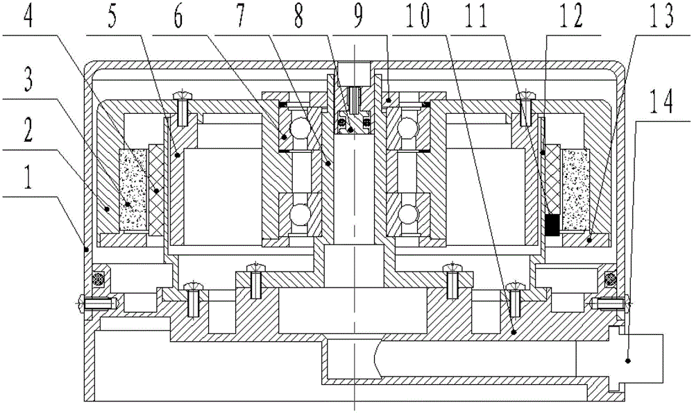
[0016] The present invention will be further described below in conjunction with the accompanying drawings.

[0017] See attached figure 1 , the rim-driven reaction flywheel of the present invention is mainly composed of a static part and a rotating part, and the static part includes: a vacuum shell 1, a winding 4, an inner ring part of a bearing 6, a mounting shaft 7, a miniature vacuum valve 8, and a lock nut 9 , base 10, position sensor 11, armature support 12, circuit interface 14; Rotating part comprises: flywheel body 2, permanent magnet 3, inner magnetic ring 5, end magnetic ring 13, the outer ring part of bearing 6.

[0018] Both the winding 4 and the position sensor 11 are installed on the armature bracket 12, the position sensor 11 faces the permanent magnet 3, the winding 4 and the position sensor 11 are connected with the external control circuit through the circuit interface 14 and drive the rotating part of the flywheel Rotation; the rotating part of the flywhee...


PUM


Abstract

The invention discloses a wheel rim driving type reaction flywheel, and belongs to the technical field of flywheel design. The wheel rim driving type reaction flywheel aims to solve the problems of large size and heavy weight of a flywheel in the prior art, and improves operating efficiency and operation stability of a spacecraft. The wheel rim driving type reaction flywheel comprises a vacuum shell, a winding, an installation shaft, a bearing, a miniature vacuum valve, a base, a position sensor, an armature support, a circuit connector, a flywheel body, a permanent magnet, an inner magnetism-conductive ring and an end magnetism-conductive ring, wherein the winding and the position sensor are arranged on the armature support, and the reaction flywheel is driven by a permanent magnet brushless direct current motor. The wheel rim driving type reaction flywheel is integrally located in the vacuum shell, and the rotational inertia / mass ratio of the flywheel is improved. By adopting the end magnetism-conductive ring, the eddy current effect of end leakage flux on the base is eliminated, and mechanical efficiency of the flywheel is improved. A permanent magnet brushless direct current motor stator comprising the winding and the armature support is of a slotless coreless type structure, and improves the operation efficiency and the operation stability.

Description

technical field [0001] The invention belongs to the technical field of flywheel design, and relates to a space vehicle attitude control device, in particular to a rim-driven reaction flywheel. Background technique [0002] The reaction flywheel uses its own stored momentum and the reaction moment generated when accelerating or braking to control the attitude of the spacecraft, which has the advantages of long life and high control precision. The traditional reaction flywheel is mainly based on the hub drive structure of the large inner hole disc, and the motor is often of iron core structure, which not only increases the volume and mass of the flywheel, but also causes serious eddy current loss and low efficiency of the flywheel. [0003] The third issue of "Journal of Engineering Design" in 2012 disclosed a design of a rim-driven reaction flywheel motor. The reaction flywheel motor includes a vacuum shell, a winding, a mounting shaft, a miniature vacuum valve, a base, a pos...

Claims


Application Information

Patent Timeline
Patent Type & Authority Patents(China)
IPC IPC(8): H02K7/02H02K29/06H02K29/08
CPCY02E60/16
Inventor 武俊峰王辉吴一辉
Owner CHANGCHUN INST OF OPTICS FINE MECHANICS & PHYSICS CHINESE ACAD OF SCI
Why Eureka
Try Eureka