Vacuum transmission processing equipment and method

A technology of vacuum transmission and process equipment, which is applied in the direction of conveyor objects, transportation and packaging, and final product manufacturing. It can solve problems such as reduced operational reliability, complex overall structure of equipment, and complex operational control, and achieve the effect of improving processing efficiency.

Active Publication Date: 2015-07-22
KINGSTONE SEMICONDUCTOR LIMITED COMPANY
View PDF2 Cites 0 Cited by
  • Summary
  • Abstract
  • Description
  • Claims
  • Application Information

AI Technical Summary

Problems solved by technology

[0007] The technical problem to be solved by the present invention is to overcome the vacuum transmission process equipment in the prior art, which usually requires chambers designed for the entry and exit of workpieces on both sides of the vacuum process chamber, which makes the overall structure of the equipment complex, resulting in With the defects of complicated operation control and reduced operational reliability, a vacuum transmission process equipment designed with only one inlet and outlet cavity between the vacuum process chamber and the atmospheric environment and a vacuum transmission process realized by using the vacuum transmission process equipment are provided. method

Method used


Image

  • Vacuum transmission processing equipment and method
  • Vacuum transmission processing equipment and method
  • Vacuum transmission processing equipment and method

Examples


Embodiment Construction

[0041] The preferred embodiments of the present invention are given below in conjunction with the accompanying drawings to describe the technical solution of the present invention in detail.

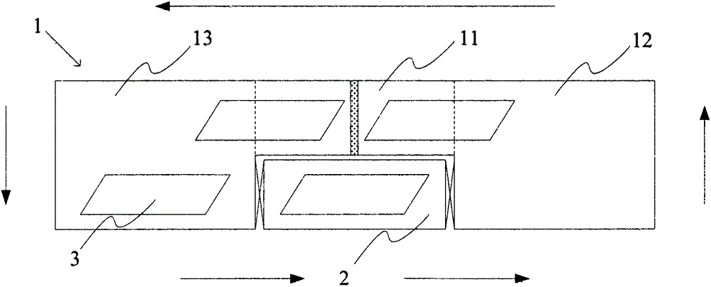
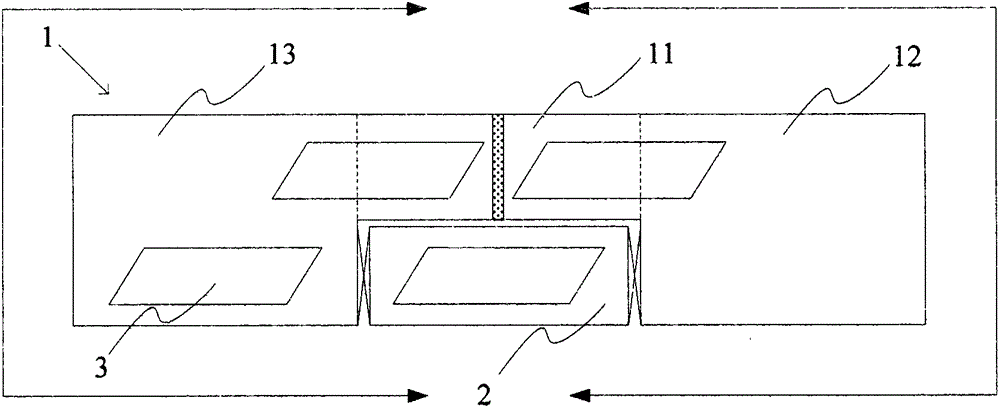
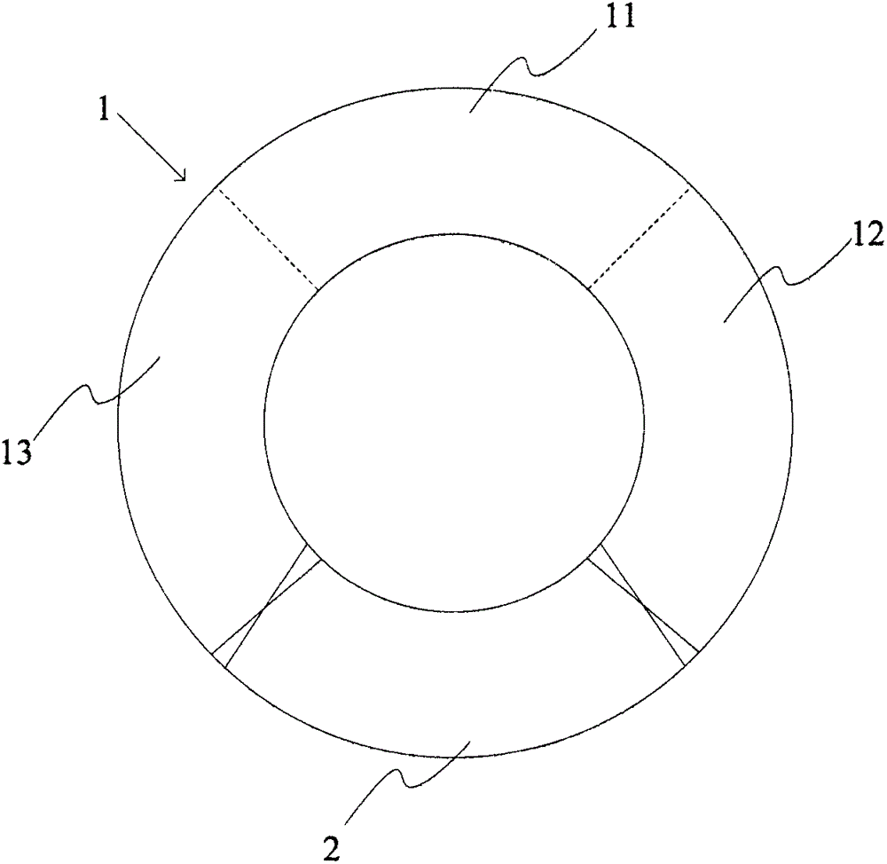
[0042] refer to figure 1 and figure 2 As shown, the vacuum transfer process equipment of the present invention mainly includes a vacuum process chamber 1 , an access chamber 2 and a plurality of transfer platforms 3 .

[0043] The vacuum process chamber 1 includes a processing area 11 ( figure 1 and figure 2 The area enclosed by the dotted line), a first waiting area 12 located on one side of the processing area 11 and a second waiting area 13 located on the other side of the processing area 11 .

[0044] One or more than two processing devices are arranged in the processing area 11, and each processing device can generate a processing medium. When the workpiece enters the effective range of the processing medium ( Figure 1-12 When the effective action range of the processing medi...


PUM


Abstract

The invention discloses vacuum transmission processing equipment and a vacuum transmission processing method. The equipment comprises a vacuum processing cavity, a workpiece inlet and outlet cavity and a plurality of transmission platforms, wherein the vacuum processing cavity comprises a processing region, a first waiting region and a second waiting region; the workpiece inlet and outlet cavity can be switched between an atmospheric state and a vacuum state; the transmission platforms are used for bearing workpieces to enable the workpieces to enter the workpiece inlet and outlet cavity from the atmospheric state, and enable the workpieces to enter the processing region from the workpiece inlet and outlet cavity through the first waiting region or the second waiting region so as to complete workpiece processing in the processing region, and enable the workpieces to move back to the workpiece inlet and outlet cavity from the processing region through the first waiting region or the second waiting region and then enable the workpieces to move back to the atmospheric environment from the workpiece inlet and outlet cavity; and each transmission platform is used for sequentially and continuously completing workpiece processing in the processing region. According to the invention, the effect of enabling the workpieces to continuously enter and exit the vacuum environment, and continuous processing on the workpieces are implemented only by designing one workpiece inlet and outlet cavity. Therefore, 100 percent of utilization on a processing medium is implemented, and processing efficiency is further greatly improved.

Description

technical field [0001] The invention relates to vacuum process technology, in particular to a vacuum transmission process equipment and a vacuum transmission process method realized by using the vacuum transmission process equipment. Background technique [0002] New energy is one of the five most decisive technological fields in the world's economic development in the 21st century, and solar energy is a clean, efficient and inexhaustible new energy. In the new century, governments of all countries regard the utilization of solar energy resources as an important content of the national sustainable development strategy. Photovoltaic power generation has many advantages such as safety, reliability, no noise, no pollution, less constraints, low failure rate, and easy maintenance. In recent years, with the rapid development of the international photovoltaic power generation industry, the supply of solar wafers is in short supply, so improving the production capacity of solar waf...

Claims


Application Information

Patent Timeline
Patent Type & Authority Patents(China)
IPC IPC(8): H01L31/18H01L21/677
CPCY02P70/50
Inventor 陈炯钱锋
Owner KINGSTONE SEMICONDUCTOR LIMITED COMPANY
Why Eureka
Try Eureka