
Second-order differential gaussian pulse generator based on SRD

A Gaussian pulse and second-order differential technology, applied in electrical pulse generator circuits, electrical components, transmission systems, etc., can solve the problems of low voltage conversion rate, increased circuit size, and high voltage conversion rate, achieving simple circuit and spectrum utilization. high rate effect

Active Publication Date: 2013-07-31
李冀
View PDF6 Cites 8 Cited by
  • Summary
  • Abstract
  • Description
  • Claims
  • Application Information

AI Technical Summary

Problems solved by technology

The circuit uses double-parallel stubs to obtain a narrow pulse of the first order differential. The double resistance load makes the ringing of the pulse smaller, but the peak-to-peak value of the pulse is less than 600mV, and the voltage conversion rate is low.
[0005] Document "NOVEL LOW COST HIGHER ORDER DERIVEACTIVE GAUSSIAN PULSE GERATOR CIRCUIT" (Low Z N, Cheong J H, Law C L. Novel low cost higher order derivative Gaussian pulse generator circuit[C] / / Communications Systems, 2004. ICCS 2004. The Ninth International Conference on. IEEE, 2004: 30-34.) gave a Gaussian narrow pulse based on a parallel SRD structure, which was shaped by a 5th-order bandpass filter to achieve a high-order differential Gaussian pulse, but the bandpass filter Forming networks increase circuit size and cost
[0006] According to the current research, there is no ideal technical solution for the high-order differential Gaussian pulse generator with high voltage conversion rate and simple structure.

Method used


Image

  • Second-order differential gaussian pulse generator based on SRD
  • Second-order differential gaussian pulse generator based on SRD
  • Second-order differential gaussian pulse generator based on SRD

Examples


Embodiment Construction

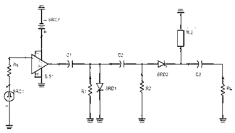
[0027] Such as figure 1 As shown, the whole circuit is composed of clock source 1, driving circuit 2, differential circuit 3, SRD Gaussian narrow pulse generating circuit 4, and second-order differential Gaussian pulse shaping circuit 5. The oscillator is composed of the negative terminal of the DC power supply DC grounded, the positive terminal connected to the power terminal of the clock oscillator, the ground terminal of the clock oscillator grounded, the output terminal connected in series with a resistor Rs of about 10Ω, and the output of the clock oscillator is a square wave signal.

[0028] Such as figure 2 As shown, the input pin of the drive circuit 2 is connected to the resistor Rs, the power supply pin is connected to DC, and the ground terminal is grounded. The output of the drive circuit is a square wave signal. The differential circuit 3 is composed of a series capacitor C1 and a parallel resistor R1. The differential circuit 3 is connected in series to Betwee...


PUM


Abstract

The invention discloses a second-order differential gaussian pulse generator based on an SRD (Step Recovery Diode), which comprises a clock source, a drive circuit, a differentiating circuit and an SRD gaussian narrow pulse generation circuit, wherein a clock excitation signal generated by the clock source passes through the drive circuit, the differentiating circuit and the SRD gaussian narrow pulse generation circuit which are sequentially connected to form a narrow pulse signal; a second-order differential gaussian pulse shaping circuit is positioned between the SRD gaussian narrow pulse generation circuit and a load; and the narrow pulse signal outputs a subnanosecond-level second-order differential gaussian pulse signal through the second-order differential gaussian pulse shaping circuit. With the adoption of the technical scheme, the second-order differential gaussian pulse generator has the benefits that a direct current component and a low frequency component of a pulse are smaller; a spectrum utilization rate is high; a planar circuit design is adopted; the circuits are simple, small in size and easy to integrate; and the second-order differential gaussian pulse generator is suitable for a short-range ultra-wide band wireless communication system.

Description

technical field [0001] The invention relates to the technical field of pulse signal generation, in particular to an SRD-based second-order differential Gaussian pulse generator, which provides pulse signals with high radiation efficiency for ultra-wideband wireless communication systems. Background technique [0002] UWB technology is a wireless technology for data communication through nanosecond narrow pulse signals. In this type of communication system, the pulse does not need to be modulated onto the carrier, but by modulating the position of the pulse (PPM modulation), pulse amplitude (PAM ), pulse switch (OOK), etc. to achieve communication. Due to its advantages of high speed, low power consumption and low cost, it has bright application prospects in many fields such as precise positioning, ground penetrating radar, and nondestructive testing. [0003] Among the key technologies of ultra-wideband communication, narrow pulse signal generation technology has always bee...

Claims


Application Information

Patent Timeline
IPC IPC(8): H03K3/02H04B1/7163
Inventor 李冀
Owner 李冀
Learn More