Vacuum pumping system

A vacuum pump, vacuum technology, applied in the direction of pump, pump components, pump control, etc., can solve the problems of multi-power, consumption and so on

Inactive Publication Date: 2013-07-31
EDWARDS LTD
View PDF4 Cites 3 Cited by
  • Summary
  • Abstract
  • Description
  • Claims
  • Application Information

AI Technical Summary

Problems solved by technology

However, such pumps are usually larger and consume more power

Method used


Image

  • Vacuum pumping system
  • Vacuum pumping system
  • Vacuum pumping system

Examples


Embodiment Construction

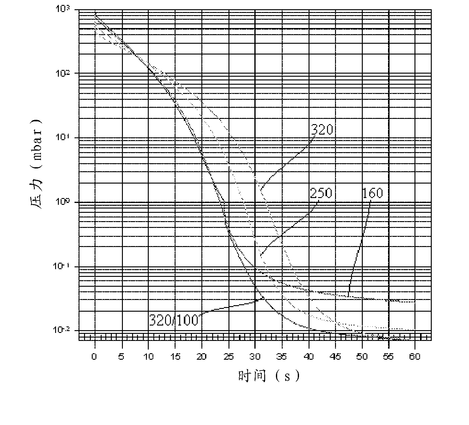
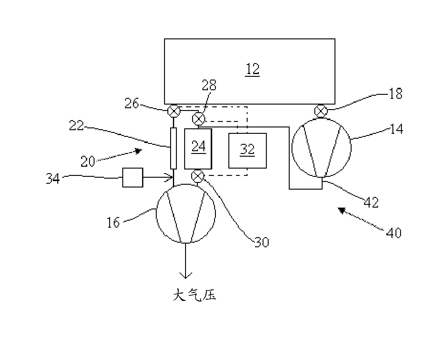
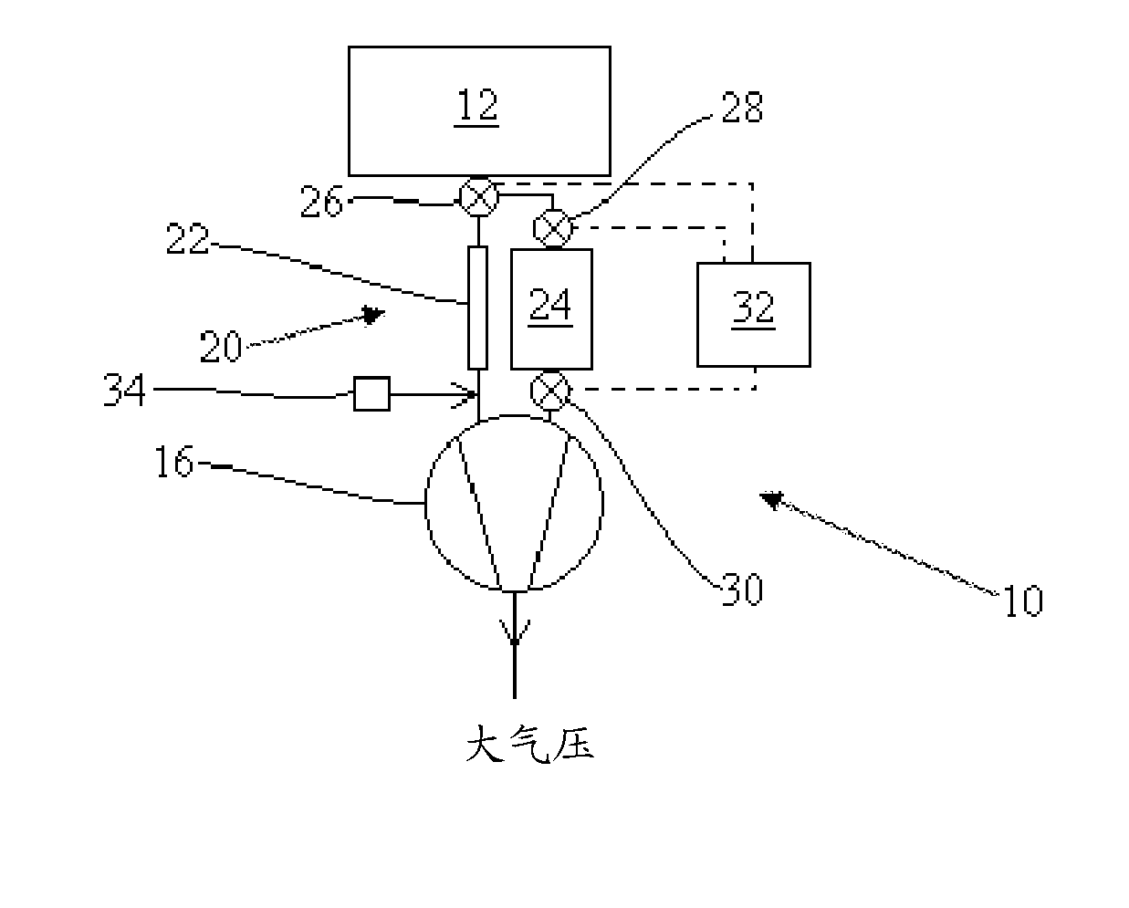
[0013] Referring to FIG. 1 , a vacuum pumping system 10 is shown for evacuating a vacuum chamber 12 . The vacuum pumping system includes a vacuum pump 16, such as a Roots pump, a claw pump or a scroll pump, for evacuating the vacuum chamber 12 to between about 1 mbar and 0.01 mbar. Two or more such pumps can be arranged in series or in parallel, and the term vacuum pump should be interpreted accordingly. A plurality of forelines 20 or conduits connect the vacuum pump 16 to the vacuum chamber 12 for delivering fluid from the chamber to the vacuum pump. The first foreline arrangement includes one or more forelines and has a first overall cross-sectional area for conveying fluid. During the rough vacuum phase of chamber evacuation, a first foreline arrangement may be connected for delivering gas to the vacuum pump. The second foreline arrangement includes one or more forelines and has a second overall cross-sectional area. During the higher vacuum phase of chamber evacuation, ...


PUM


Abstract

The present invention relates to a vacuum pumping system (10) for evacuating a vacuum chamber (12), the system comprising: a vacuum pump (16); and a plurality of forelines (22, 24) for conveying gas to the vacuum pump wherein in a first low vacuum stage of chamber evacuation a first foreline arrangement (22) can be connected for conveying gas to the vacuum pump and in a second higher vacuum stage of chamber evacuation a second foreline arrangement (22, 24) comprising one or more of said forelines can be connected for conveying gas to the vacuum pump, wherein the second foreline arrangement has a total cross-sectional area for conveying fluid which is larger than a total cross-sectional area of the first foreline arrangement.

Description

technical field [0001] The invention relates to a vacuum pumping system for evacuating a vacuum chamber. Background technique [0002] The manufacture of many items requires the use of vacuum chambers. For example, the processing of silicon wafers takes place in a high vacuum. In addition, devices such as flat panel display devices and solar cells need to be processed in a vacuum chamber. In these latter instances, the vacuum chamber may need to have a larger volume to handle larger items. Typically, the pressure in the vacuum chamber needs to be cycled between atmospheric pressure (1 bar) and process pressure (eg, 0.01 mbar) as part of the process cycle. In order to improve manufacturing speed and efficiency, it is desirable to utilize a vacuum pumping system to increase the rate at which gas is evacuated from the vacuum chamber. [0003] The vacuum pumping system may include a vacuum pump and a foreline connecting an inlet of the vacuum pump to the vacuum chamber so th...

Claims


Application Information

Patent Timeline
Patent Type & Authority Applications(China)
IPC IPC(8): F04C25/02
CPCF04C14/00F04B37/14F04C29/12F04C25/02F04C2/00F04C2270/18F04C2220/30F04C29/0035
Inventor M·A·加尔特里D·A·图雷尔
Owner EDWARDS LTD
Why Eureka
Try Eureka