Valve body and bonnet connection torsion dispensing assembly machine

A torque point, valve body technology, applied in the direction of assembly machines, connecting components, devices for coating liquid on the surface, etc. Uniformity and other issues, to achieve the effect of high connection firmness, saving processing time, and uniform coating

Inactive Publication Date: 2013-08-07
ZHEJIANG VALOGIN TECH
View PDF5 Cites 32 Cited by
  • Summary
  • Abstract
  • Description
  • Claims
  • Application Information

AI Technical Summary

Problems solved by technology

When the valve body and bonnet are assembled, it is generally necessary to apply anaerobic adhesive between the two, so that the bonding between the valve body and the bonnet is high, and it can seal the gap between the valve body and the bonnet. However, the valve body cap connection torque assembly machine with this structure cannot automatically apply the anaerobic adhesive, and the application of the anaerobic adhesive still needs to be manually applied by the operator, and the efficiency of the application is low. Oxygen adhesives have the disadvantage of uneven glue application, which leads to problems such as weak bonding and poor sealing effect of some valve bodies and bonnets after connection

Method used


Image

  • Valve body and bonnet connection torsion dispensing assembly machine
  • Valve body and bonnet connection torsion dispensing assembly machine
  • Valve body and bonnet connection torsion dispensing assembly machine

Examples


Embodiment 1

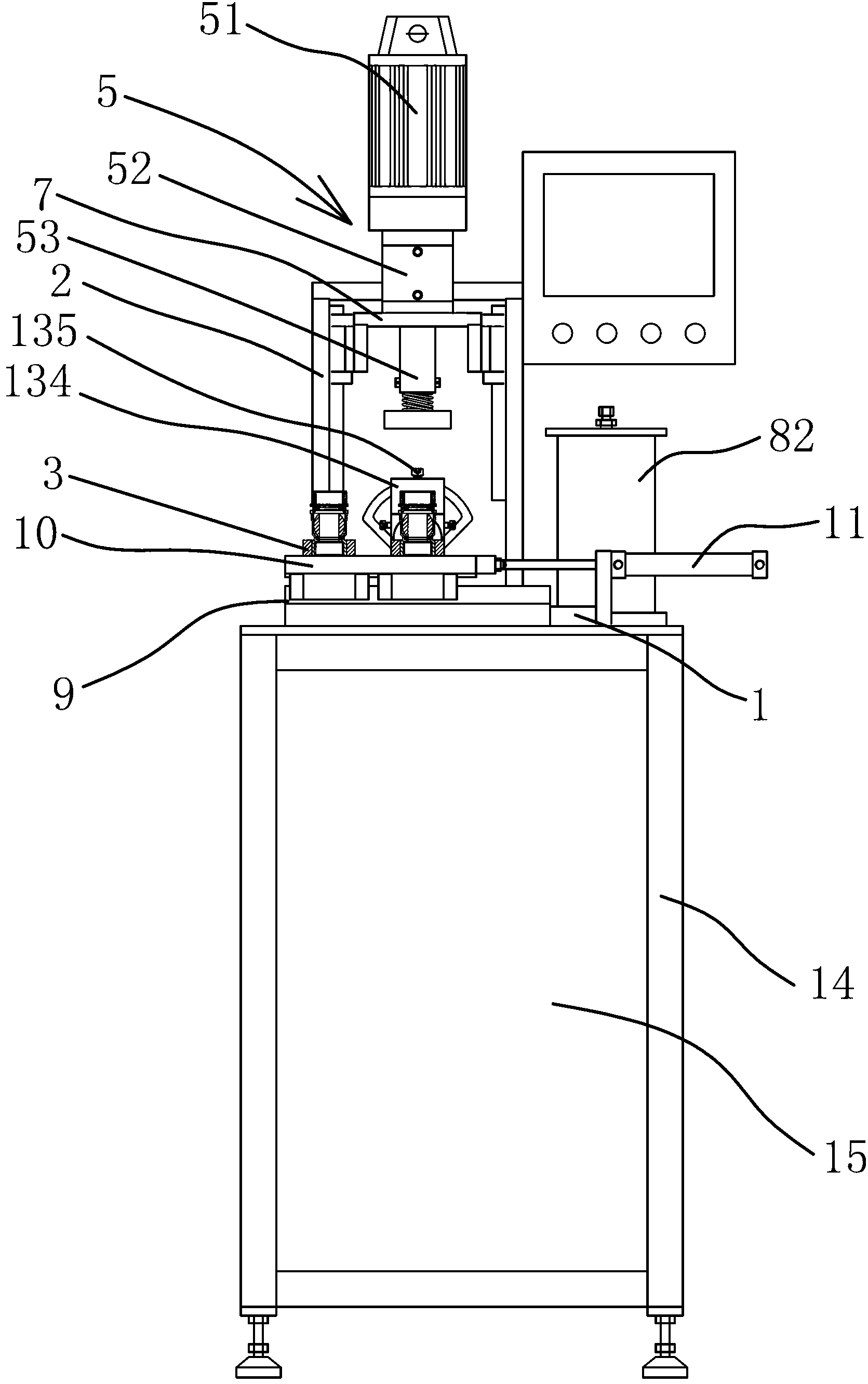
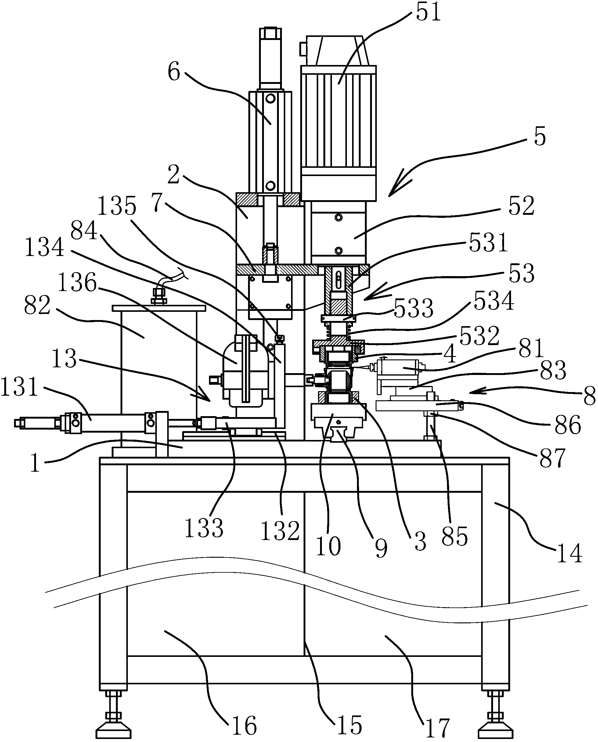
[0032] This assembly machine is mainly used to connect the valve body and bonnet of the valve, such as figure 1 , figure 2 As shown, it includes workbench 1, bracket 2, upper mold body 4, lower mold body 3, lifting cylinder 6, lifting slide table 7, torque control mechanism 5, glue dispensing mechanism 8, valve stem rotation mechanism 13, frame 14 and chassis 15.

[0033] There is a cabinet 15 in the frame 14, one side of the cabinet 15 is an air control cabinet 16, and the other side is an electric control cabinet 17, and the top of the frame 14 is horizontally fixed with a workbench 1. The two sides of the workbench 1 are symmetrically fixed with vertical boards respectively, the tops of the two vertical boards are connected by a horizontal board to form a support 2, and a lifting cylinder 6 is installed upside down above the horizontal board, and the piston rod of the lifting cylinder 6 passes through the horizontal board , the end place of piston rod is fixedly connecte...

Embodiment 2

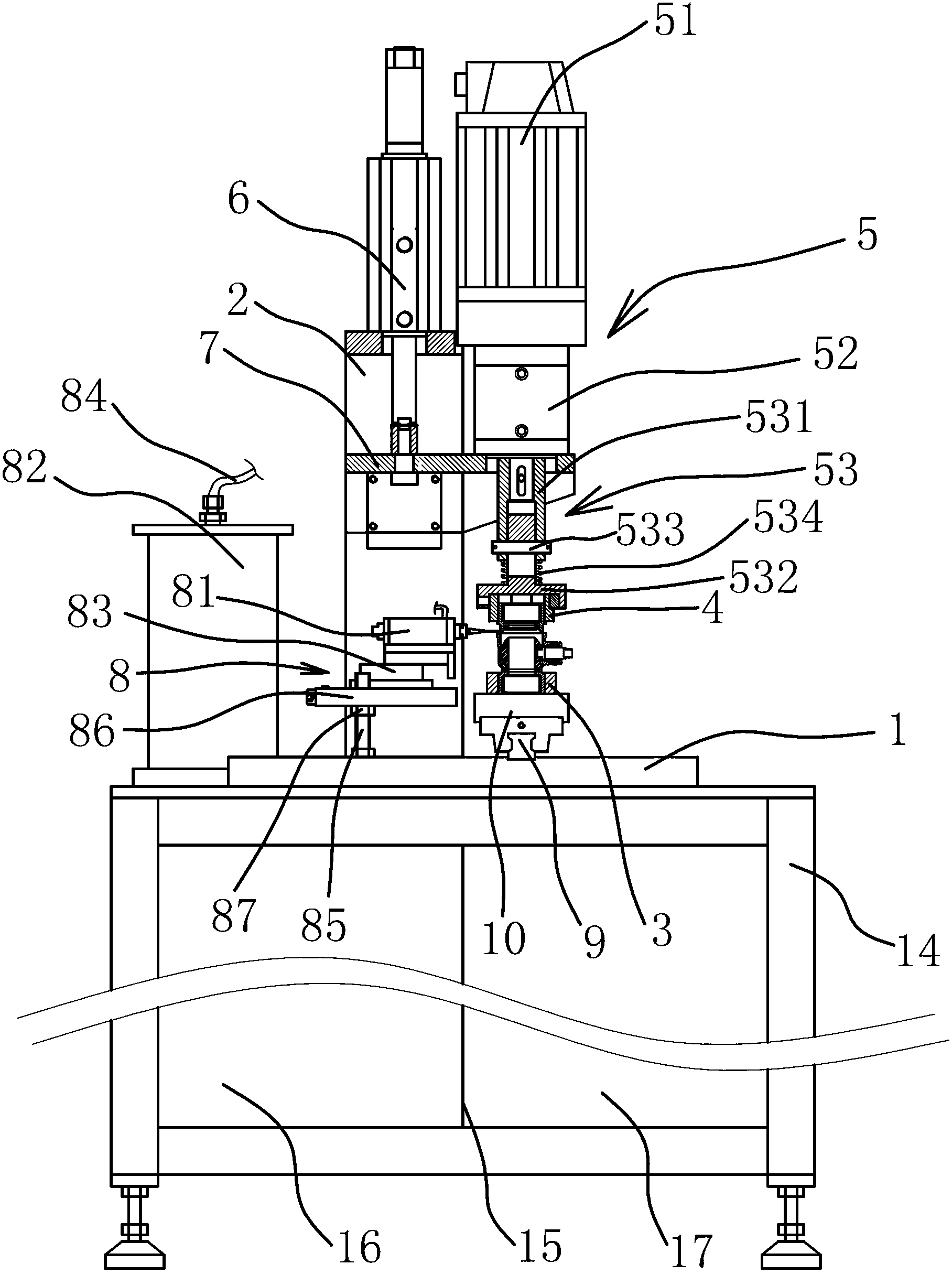
[0040] Such as image 3 As shown, the structure and principle of this embodiment are basically the same as that of Embodiment 1. The difference is that this assembly machine does not have a valve stem rotation mechanism, and the injection valve, slide cylinder, adjustment rod, adjustment block and nut are located Embodiment A valve stem rotation mechanism is located on the other side of the lower die body operator. This structure makes the operation convenient for the operator when loading and unloading materials.

Embodiment 3

[0042] Such as Figure 4 As shown, the structure and principle of this embodiment are basically the same as that of Embodiment 1, the difference is that in this embodiment, the lower die body 3 is fixed on the turntable 12, and the center of the turntable 12 is connected with the power mechanism. The motive mechanism is a rotary cylinder. In actual production, the power mechanism can be a combination of a stepping motor and a reducer, or a combination of a motor and a divider. In this embodiment, the number of lower mold bodies 3 is 4. The circumferential direction is equidistantly arranged, and the slide table cylinder 83 is fixed on the non-rotating axis position of the turntable 12, and the rotating cylinder drives the turntable to rotate so that the lower die body 3 is located directly below the upper die body 4 in turn to realize the processing of the valve.


PUM


Abstract

The invention provides a valve body and bonnet connection torsion dispensing assembly machine, belongs to the technical field of valve production devices and solves problems that the existing valve body and bonnet connection assembly machine cannot achieve automatic gluing. The valve body and bonnet connection torsion dispensing assembly machine comprises a worktable and a support fixed on the worktable, wherein a lower die body is arranged on the worktable, an upper die body is arranged right above the lower die body and is fixed on the lower portion of a torsion control mechanism used for controlling rotating of the upper die body, a lifting cylinder is fixedly connected onto the support, a lifting sliding table is fixedly connected at the end of a piston rod of the lifting cylinder, the torsion control mechanism is fixed on the lifting sliding table, and a dispensing mechanism is arranged on the side portion of the lower die body. The valve body and bonnet connection torsion dispensing assembly machine has the advantages of having double functions of valve bonnet screwing and gluing, being high in automation and work efficiency and the like.

Description

technical field [0001] The invention belongs to the technical field of valve manufacturing equipment, and relates to an assembly machine, in particular to a valve body cap connection torque dispensing assembly machine. Background technique [0002] With the rapid development of social economy, the competitiveness of labor-intensive valve enterprises is getting weaker and weaker. At present, there is a problem of difficult recruitment in the eastern coastal areas, which forces enterprises to develop in the direction of production automation and semi-automation to improve production efficiency. Reduce labor costs. [0003] A valve generally includes a valve body and a bonnet, and the valve body and bonnet are connected by threads. There are existing assembly machines for connecting the valve body and the bonnet. For example, Chinese patent literature discloses a torque assembly machine for connecting the valve body and cap [application number: 201210002776.8; Application publ...

Claims


Application Information

Patent Timeline
Patent Type & Authority Applications(China)
IPC IPC(8): F16B11/00B05C5/02B23P21/00
Inventor 戴美云张凤萍蒋炜敏李明吴金贵田保国舒平冬
Owner ZHEJIANG VALOGIN TECH
Why Eureka
Try Eureka