Free piston linear generator based on waste heat utilization

A technology of linear generators and pistons, applied to internal combustion piston engines, engine components, combustion engines, etc., can solve problems such as energy loss, and achieve the effects of protecting the environment and saving energy

Active Publication Date: 2013-08-07
BEIJING INSTITUTE OF TECHNOLOGYGY
7 Cites 21 Cited by

AI-Extracted Technical Summary

Problems solved by technology

At the same time, during the working process of the free-piston linear generator, the exhaust gas produced by the general internal combustion engine is...

Abstract

The invention relates to a free piston linear generator based on waste heat utilization and belongs to the technical field of energy power. The free piston linear generator specifically comprises a free piston combustion engine, the linear generator and a waste gas expansion cylinder. The free piston combustion engine comprises an oil atomizer, a gas inlet, a gas outlet, a piston and a combustion engine cylinder. The linear generator comprises a motor stator and a motor rotor. A waste gas utilizing assembly comprises a gas guiding pipe, a gas inlet door, a gas outlet door, a reset piston, a reset cylinder and a water sprayer. A working process includes a starting process and a steady operation process. In a cold start-up process, a linear engine works in a motor mode and drives a device to be started and work. In the steady operation process, the linear generator works in a generator mode, the combustion engine works to drive the linear generator to do work and generate power, then a moving assembly returns to a top dead center through a waste gas waste heat utilization method, and next circulation movement is conducted. The free piston linear generator has the advantages of being capable of protecting environment and saving energy.

Application Domain

Technology Topic

Image

  • Free piston linear generator based on waste heat utilization

Examples

  • Experimental program(1)

Example Embodiment

[0017] Example 1
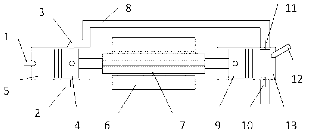
[0018] A free-piston linear generator based on waste heat utilization mainly includes: a free-piston internal combustion engine, a linear generator, and an exhaust gas expansion cylinder. Its free-piston internal combustion engine mainly includes: injector 1, air inlet 2, exhaust port 3, piston 4, internal combustion engine cylinder 5; linear generator includes: motor stator 6, motor mover 7; exhaust gas utilization components include: bleed pipe 8. Intake valve 11, exhaust valve 10, return piston 9, return cylinder 13, water injector 12.
[0019] The specific connection relationship is as follows: the return piston 9 is placed in the return cylinder 13; the water sprayer 12 is installed on the return cylinder 13; 11 is connected; the return piston 9 is connected with one end of the linear motor mover 7; the other end of the linear motor mover 7 is connected with the piston 4 of the free piston internal combustion engine, and the return piston 9, the motor mover 7 and the internal combustion engine piston 4 constitute a moving component.
[0020] 1) Startup process. At this time, the linear generator works in the motor mode, the motor mover 7 pushes the moving component to move, and the piston 4 compresses the gas in the cylinder 5 of the internal combustion engine. The injector 1 of the free-piston internal combustion engine then injects fuel into the cylinder. The fuel burns under high pressure to perform work, which pushes the moving components to move in the opposite direction. The start-up process is now complete.
[0021] 2) Running process. During this stage of work, the system works in a reciprocating manner. At the beginning of a cycle, the piston 4 of the internal combustion engine is at the top dead center position, the fuel injector 1 injects fuel into the cylinder, and the high-pressure gas after combustion pushes the moving component to move. At this time, the linear generator works outwards and outputs electric energy in generator mode. And the exhaust valve 10 of the recovery cylinder is opened, the intake valve 11 is closed, and the gas pressure in the recovery cylinder 13 is consistent with the environment, maintaining a relatively low pressure state. When the gas in the internal combustion engine cylinder 5 expands for a period of time, its exhaust port 3 is opened, and the high temperature and high pressure exhaust gas is introduced into the intake pipe 8 . At the same time, close the exhaust valve 10 of the return cylinder and open its intake valve 11; open the intake port 2 of the free-piston internal combustion engine to ventilate the internal combustion engine cylinder 5, and the moving component reaches the bottom dead center. When the exhaust gas enters the recovery cylinder 13 through the intake pipe 8, the exhaust valve 11 of the recovery cylinder is closed, and the water sprayer 12 sprays water into the recovery cylinder 13. The water absorbs heat from the high-temperature exhaust gas and vaporizes, forming high-pressure steam and starting to push the moving components back to the top dead center. Then start the next cycle.

PUM

no PUM

Description & Claims & Application Information

We can also present the details of the Description, Claims and Application information to help users get a comprehensive understanding of the technical details of the patent, such as background art, summary of invention, brief description of drawings, description of embodiments, and other original content. On the other hand, users can also determine the specific scope of protection of the technology through the list of claims; as well as understand the changes in the life cycle of the technology with the presentation of the patent timeline. Login to view more.

Similar technology patents

Classification and recommendation of technical efficacy words

  • Protect environment
  • Energy saving

Method for recovering rare earth from waste rare earth luminescent material

InactiveCN102660688AHigh recovery rateProtect environmentGlass recyclingCerium oxides/hydroxidesRare-earth elementGlass matrix
Owner:UNIV OF SCI & TECH BEIJING

Environmental protective covering for electrical power connectors

InactiveUS7771221B1Efficient cable routingProtect environmentCouplings bases/casesEngineeringAll terrain vehicles
Owner:BLACKWELL DONALD A
Why Eureka
Try Eureka