
A main transmission mechanism of a permanent magnet and gear compound transmission continuously variable transmission

A continuously variable transmission and compound transmission technology, applied in gear transmissions, transmissions, components with teeth, etc., can solve the problems of high material requirements, low efficiency, and high manufacturing accuracy, and achieve system weight reduction and high system efficiency. , the effect of structure simplification

Inactive Publication Date: 2015-09-30
NANJING INST OF TECH
View PDF6 Cites 0 Cited by
  • Summary
  • Abstract
  • Description
  • Claims
  • Application Information

AI Technical Summary

Problems solved by technology

[0002] The automatic transmission for automobiles mainly uses a hydraulic torque converter to achieve stepwise stepless transmission. However, the manufacturing precision of the hydraulic torque converter is high and the volume is large. Although it can realize transmission at a large speed difference, the efficiency is low, especially When running at low speed; the CVT for automobiles is based on the friction mechanism, generally metal belt or chain, the disadvantages are high material requirements, high manufacturing precision and low efficiency, although it can achieve the best match with the engine, but The overall fuel-saving effect is not obvious; another kind of automatic transmission for vehicles, AMT, is a mechanical automatic transmission. Its shifting quality and comfort need to be improved to meet the comfort needs of passenger cars. Passenger cars: There is a problem with the dual-clutch automatic transmission for vehicles, and power interruption will occur due to heat generation, so it is no longer popular in the market

Method used


Image

  • A main transmission mechanism of a permanent magnet and gear compound transmission continuously variable transmission
  • A main transmission mechanism of a permanent magnet and gear compound transmission continuously variable transmission

Examples


Embodiment Construction

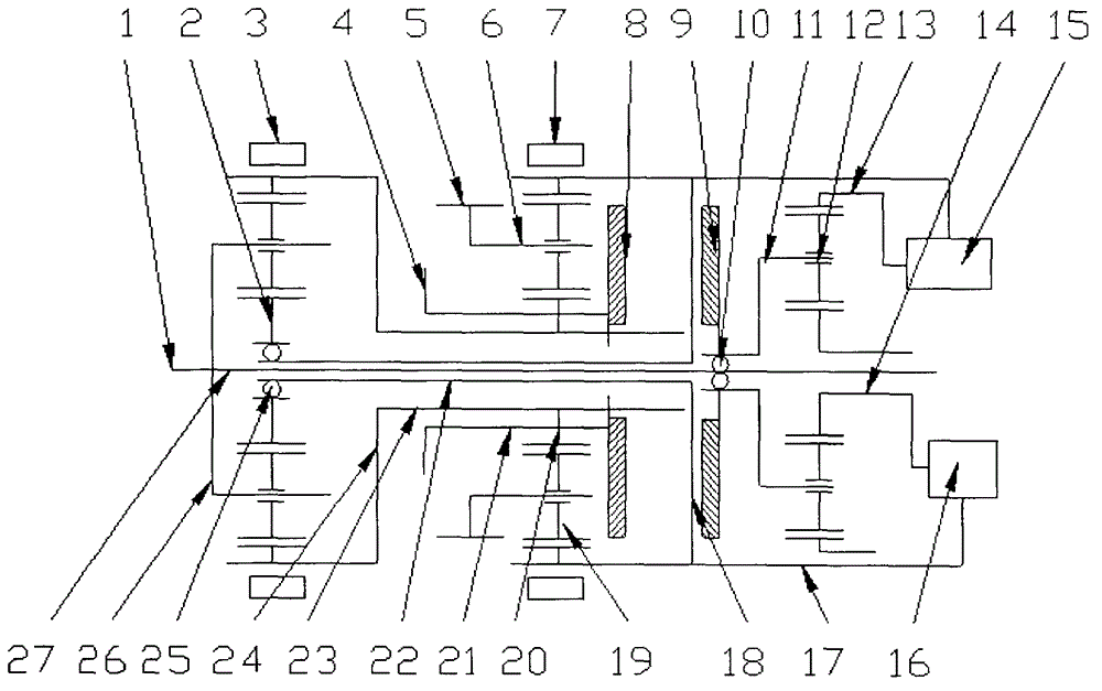
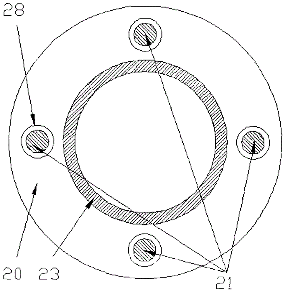
[0021] Refer to attached figure 1 ~ attached figure 2 , the structural characteristics of the main transmission mechanism of a permanent magnet and gear compound transmission continuously variable transmission are (as attached figure 1 ~ attached figure 2 ): The number of teeth of the front inner ring gear of the front planetary row 2 is 78, the number of teeth of the front sun gear is 30, the number of teeth of the front planetary gear is 24, the number of teeth of the inner ring gear of the rear planetary row 19 is 78, the number of teeth of the rear sun gear 20 is 30, and the number of teeth of the rear sun gear is 30. The number of planetary gear teeth is 24, the speed ratio range is 6.76, the size of the active element 8 of the permanent magnetic coupler and the active element 9 of the permanent magnetic coupler are 130mm in outer diameter, and 12 pieces of NdFeB permanent magnets are respectively installed, and the active element of the permanent magnetic coupler is ...


PUM


Abstract

The invention relates to a main transmission mechanism of a permanent magnet and gear combined transmission continuous variable transmission device. The main transmission mechanism is particularly composed of a main transmission part composed of two combined planetary gear rows, a permanent magnet coupler, a front planet row with guide-out shafts on two sides and a front planet frame. The main transmission mechanism is particularly suitable for being used as a transmission of an automobile and is structurally characterized in that the planet frame 11 for controlling the planet row 12 is an input element, input power is relevant to a driving element 8 of the permanent magnet coupler and a shaft 27, an adjusting element is an overrunning coupler 10, and the permanent magnet coupler is installed on two sides of a thin round plate 18. The main transmission mechanism of the permanent magnet and gear combined transmission continuous variable transmission is suitable for the field of automobiles, energy-saving automobiles, new energy automobiles, urban rail vehicles, wind electricity power generation systems, aircrafts, machine tools, industrial and mineral machinery, engineering machinery and the like.

Description

technical field [0001] The invention relates to a main transmission mechanism of a permanent magnet and gear compound transmission continuously variable transmission, which utilizes the non-contact characteristics of the permanent magnet transmission and realizes the purpose of small volume and compact structure when applied to planetary gear differential continuously variable transmission , using the characteristics of planetary gears with two degrees of freedom to divide and merge power, realize the stepless change of the speed ratio of the main transmission line movement, divide a part of the power of the main transmission branch, and pass it to the other branch of the main transmission by controlling the transmission part , use the permanent magnet slip transmission mechanism connected with the control transmission part to close the planetary gear differential transmission mechanism, change the transmission torque of the permanent magnet slip transmission mechanism to achie...

Claims


Application Information

Patent Timeline
Patent Type & Authority Patents(China)
IPC IPC(8): F16H3/76F16H3/72F16H61/28
Inventor 邹政耀吕云嵩赵伟军张日波华传军
Owner NANJING INST OF TECH
Learn More