Conduction oil internal circulation type heating roller

A technology of heat conduction oil and heating rollers, which is applied in the field of heating rollers, can solve the problems of high energy consumption and poor heating effect, achieve high heat conduction, improve service life, and prevent excessive centrifugal force

Inactive Publication Date: 2013-08-07
WEIHAI FENGTAI NEW MATERIAL SCI & TECH
View PDF6 Cites 9 Cited by
  • Summary
  • Abstract
  • Description
  • Claims
  • Application Information

AI Technical Summary

Problems solved by technology

[0004] In order to overcome the technical problems of high energy consumption and poor heating effect of the heating method currently used by the heating roller, the present invention provides a heat-conducting oil internal circulation heating roller that combines the electric heating method and the heat-conducting oil circulation method

Method used


Image

  • Conduction oil internal circulation type heating roller
  • Conduction oil internal circulation type heating roller
  • Conduction oil internal circulation type heating roller

Examples


Embodiment 1

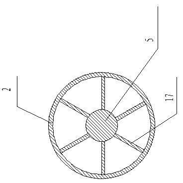
[0022] Such as figure 1 As shown, the heat transfer oil internal circulation heating roller includes an outer cylinder body 1, end plates 3 welded and closed at both ends of the outer cylinder body, and left and right support shafts 5 located at both ends of the outer cylinder body.

[0023] Such as figure 1 As shown, an inner cylinder 2 coaxial with the outer cylinder is provided inside the outer cylinder 1, the two ends of the inner cylinder 2 are welded to the end plates, and a heat transfer oil chamber 8 is formed between the outer cylinder and the inner cylinder. The heat-conducting oil chamber 8 is filled with heat-conducting oil.

[0024] Such as figure 1 As shown, the left and right support shafts 5 respectively pass through the end discs 3 at both ends of the outer cylinder and penetrate into the inner cylinder. In order to strengthen the connection strength between the support shaft 5 and the end disc 3, a support shaft is provided inside the inner cylinder 2. Rib...

Embodiment 2

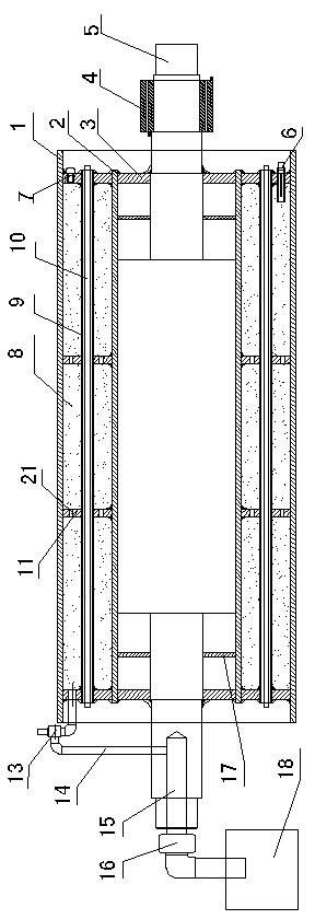
[0035] Such as figure 2 As shown, the heating roller provided in this embodiment includes an outer cylinder body 1 , end plates 3 welded and closed at both ends of the outer cylinder body, and left and right support shafts 5 located at both ends of the outer cylinder body.

[0036] Such as figure 2 As shown, in this embodiment, the heating roller is also provided with a heat transfer oil injection hole, an oil discharge pipe, a safety valve, and a thermocouple, and its design and arrangement are the same as in Embodiment 1, except for the heating device in the heat transfer oil chamber.

[0037] Such as figure 2 As shown, the heating device in this embodiment is that the outer surface of the inner cylinder 2 is circumferentially provided with a plurality of tubes 9 coaxial with the inner tube, and the tubes 9 extend toward both ends of the inner tube and pass through Through the end disks 3 at both ends, an electric heating tube 10 is installed in the hosting 9, and t...

Embodiment 3

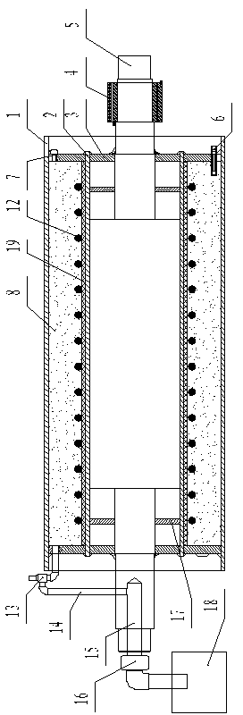
[0040] Such as image 3 As shown, the heating roller provided in this embodiment includes an outer cylinder body 1, an end plate 3 welded and closed at both ends of the outer cylinder body, left and right support shafts 5 located at both ends of the outer cylinder body, a heat transfer oil injection hole 7, an oil discharge pipe 14, The safety valve 13 and the thermocouple 6 are designed and arranged the same as the heating rollers in Embodiment 1 and Embodiment 2, and the difference also lies in the heating device in the heat-conducting oil chamber.

[0041] Such as image 3As shown, the heating device includes several hosting support rings 11 uniformly distributed along the cylinder axis in the heat transfer oil chamber, the hosting support rings 11 are sleeved on the outer surface of the inner cylinder 2, and the inside of the hosting support ring ring body and the inner cylinder The outer surface of the body 2 is fixed by welding, and the outer side of the supporting ri...


PUM


Abstract

The invention relates to a heating roller, solve the technical problems that the heating mode adopted by a conventional heating roller is high in energy consumption and poor in heating effect, and provides a conduction oil internal circulation type heating roller which comprises an outer cylinder body, end disks welded at two ends of the outer cylinder body hermetically, and left and right support shafts at two ends of the outer cylinder body. The conduction oil internal circulation type heating roller is characterized in that an inner cylinder body coaxial with the outer cylinder body is arranged in the outer cylinder body; two ends of the inner cylinder body are welded with the end disks; a conduction oil cavity is formed between the outer cylinder body and the inner cylinder body; the conduction oil cavity is filled with conduction oil; a conduction oil injection hole is formed at one of the two end disks at two ends of the outer cylinder body; a heating device is arranged in the conduction oil cylinder, and is connected with conductive slip rings on the support shafts through a lead wire. The conduction oil internal circulation type heating roller has the advantages that the heat conduction is efficient, the energy consumption is reduced, and the service life of the heating roller is prolonged greatly.

Description

[0001] technical field [0002] The invention relates to a heating roller, in particular to a heat conduction oil internal circulation heating roller. Background technique [0003] Heating rollers, generally metal round rollers, are used in many industries such as pharmaceuticals, food, ironing, drying, setting, textiles, printing and dyeing, non-woven fabrics, drying plastics and other mechanical equipment such as heating lamination and embossing. The heating method generally adopts electric heating or external circulation of heat transfer oil. Among them, the electric heating method is to install a heating rod inside the roller, and the roller is heated by releasing heat through the heating rod, which has poor heating effect, high energy consumption and large temperature fluctuation. However, the external circulation heating method of heat transfer oil requires a large investment, and additional heat transfer oil furnaces are required. After the heat transfer oil is heat...

Claims


Application Information

Patent Timeline
Patent Type & Authority Applications(China)
IPC IPC(8): F24H7/00F24H9/18F24H9/20H05B3/06
Inventor 钱国峰刘海庆
Owner WEIHAI FENGTAI NEW MATERIAL SCI & TECH
Why Eureka
Try Eureka