

Device and method for testing adhesive property between fiber reinforce plastic (FRP) rib and concrete under complicated stress state
A technology of stress state and testing device, which is applied in the direction of measuring device, mechanical device, instrument, etc., to achieve the effect of convenient operation and simple device
- Summary
- Abstract
- Description
- Claims
- Application Information
AI Technical Summary
Problems solved by technology
Method used
Image

Examples
Embodiment 1
[0049] Such as Figure 1-12 shown.
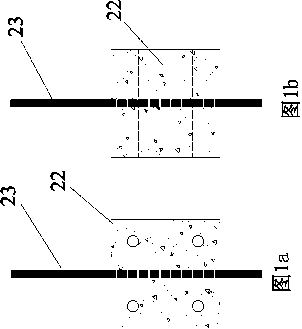
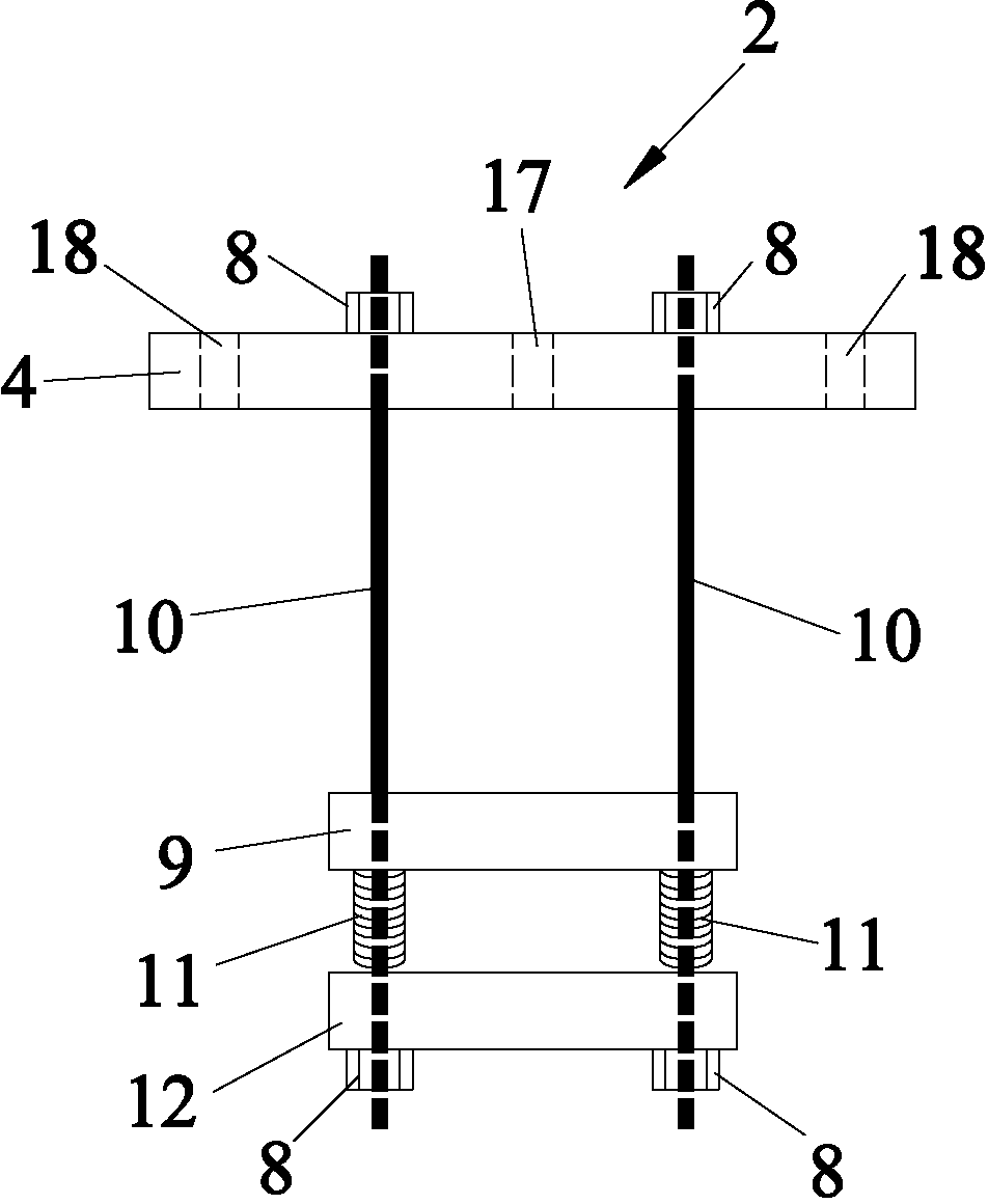
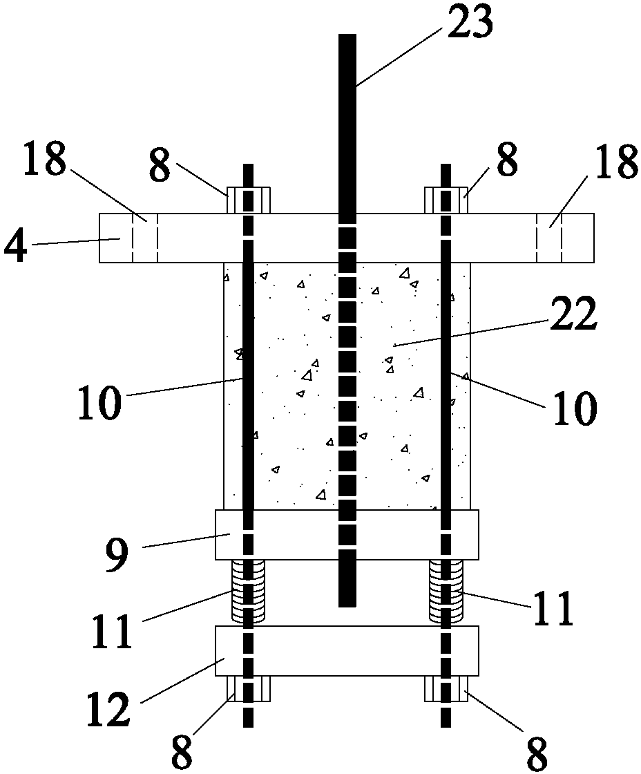
[0050] A device for testing the bonding performance of FRP bars and concrete under complex stress conditions, which includes a vertical outer frame 1 ( Figure 7 ), vertical inner frame 2 ( figure 2 ) and horizontal frame 3 ( Figure 4 ), Specimen 22 ( figure 1 ) clamp the horizontal frame 3 and then clamp it in the vertical inner frame 2, and then clamp the vertical inner frame 2 in the vertical outer frame 1, and the FRP ribs 23 of the test piece 22 pass through the top plate of the vertical outer frame 1 Link to each other with tensile testing machine afterward, the bottom tie rod 7 of vertical outer frame 1 lower end also links to each other with tensile testing machine, and the stressed direction of specimen 22 and bottom tie bar 7 is opposite. The vertical outer frame 1 ( Figure 7 ) includes a top steel plate 4, a first vertical column steel rod 5, a first bottom steel plate 6 and a bottom tie rod 7, and the first vertical ...
Embodiment 2
[0056] The invention relates to a method for testing the bonding performance of FRP tendons and concrete under complex stress conditions, which is characterized in that it includes the preparation of specimens, clamping and tensile testing.
[0057] The preparation method and steps of the test piece are as follows:
[0058] First of all, prepare for the trial mold, set a round hole in the center of the front and rear side templates of the trial mold, for passing through the FRP bars, and set four round holes at the four corners of the left and right side molds for the test mold Wear 4 PVC pipes and form reserved holes after concrete pouring. The reserved holes are used to pass through the 4 horizontal steel rods 15 of the horizontal frame 3. The purpose is to facilitate the simultaneous installation of the vertical inner frame and the horizontal frame, such as figure 1 with Image 6 ;
[0059] Second, fix the FRP bars and PVC pipes in the test mold side mold holes re...
PUM
 Abstract
Description
Claims
Application Information