Optical fiber coupling-based optical fiber rotating collimator and coaxial debugging method for mechanical axis and optical axis of optical fiber rotating collimator

A fiber collimator and fiber coupling technology, which is applied in the coupling of optical waveguides, instruments, optics, etc., can solve the problem of difficulty in debugging, and achieve the effect of reducing the difficulty of debugging.

Inactive Publication Date: 2013-08-07
HARBIN UNIV OF SCI & TECH
View PDF5 Cites 14 Cited by
  • Summary
  • Abstract
  • Description
  • Claims
  • Application Information

AI Technical Summary

Problems solved by technology

[0003] In order to solve the problem of coaxial debugging of the optical axis and the mechanical axis of the existing optical fiber collimator, the plane reflector needs to be fixed on the rotating device and an external light source is used at the same time,

Method used


Image

  • Optical fiber coupling-based optical fiber rotating collimator and coaxial debugging method for mechanical axis and optical axis of optical fiber rotating collimator
  • Optical fiber coupling-based optical fiber rotating collimator and coaxial debugging method for mechanical axis and optical axis of optical fiber rotating collimator
  • Optical fiber coupling-based optical fiber rotating collimator and coaxial debugging method for mechanical axis and optical axis of optical fiber rotating collimator

Examples


specific Embodiment approach 1

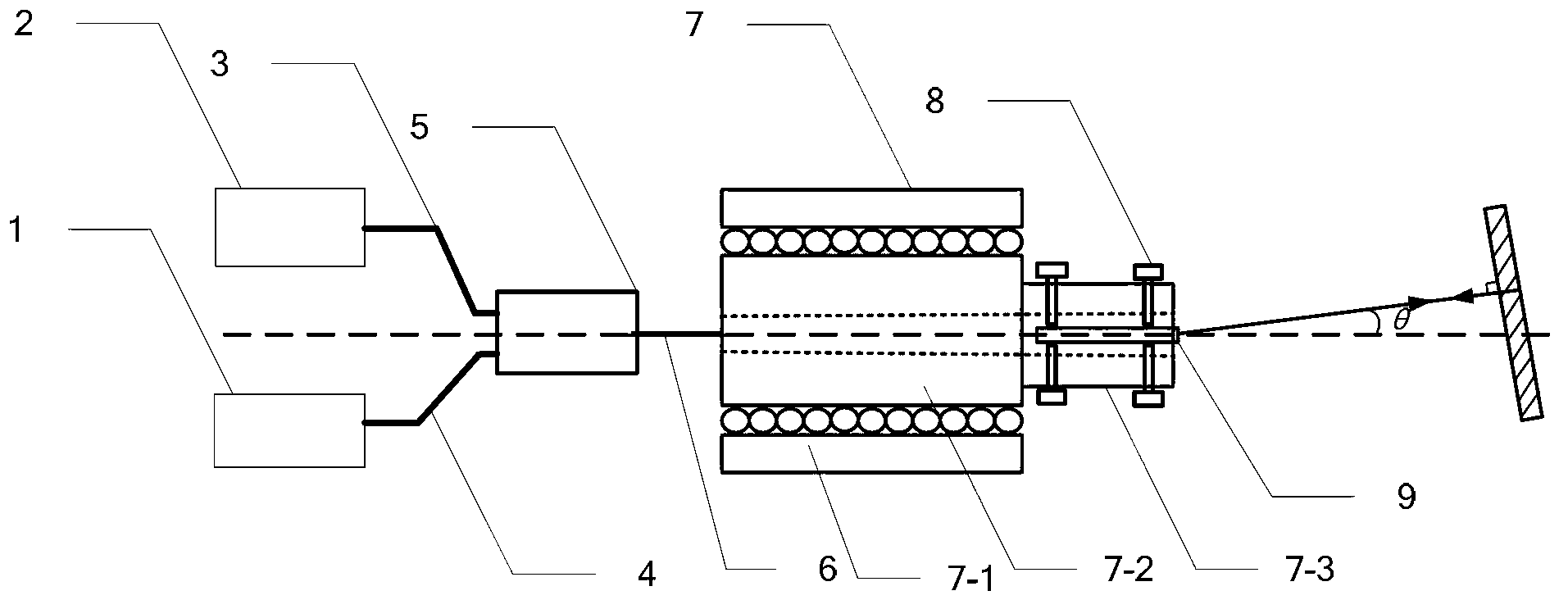
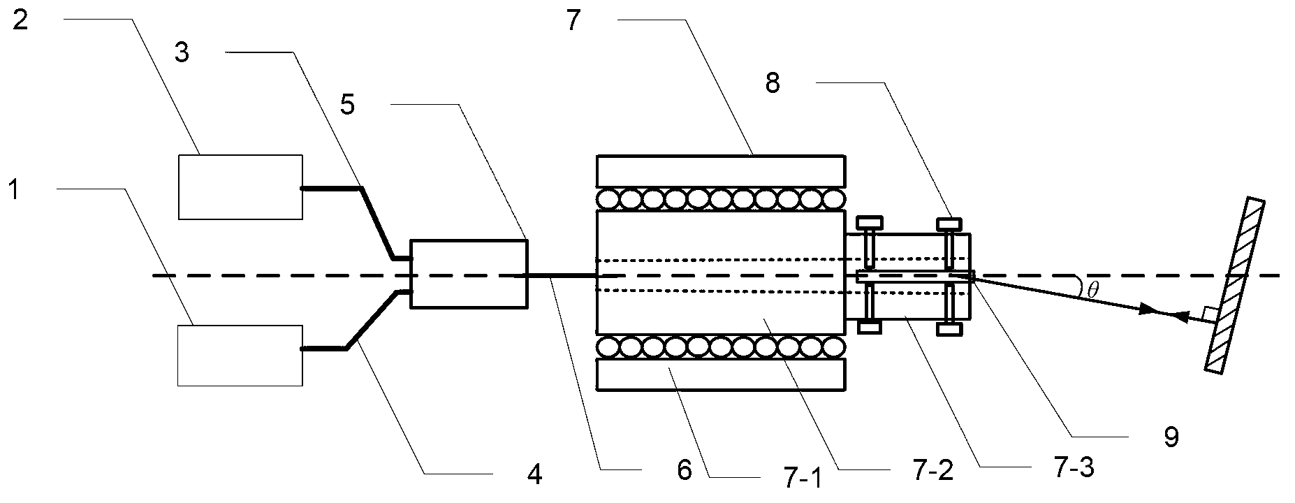
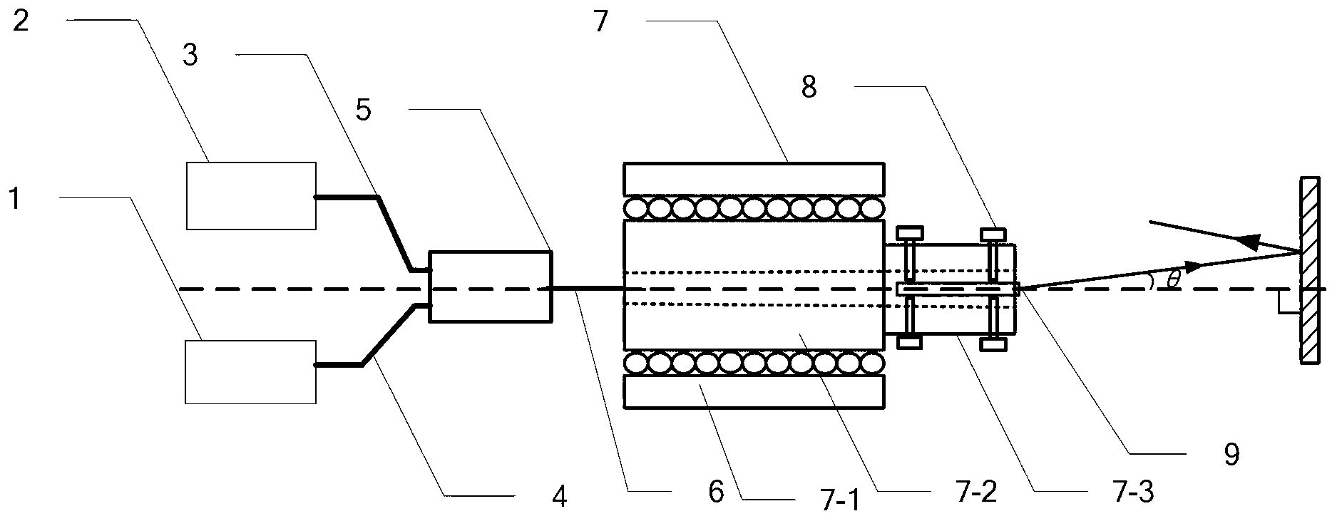
[0017] Specific Embodiment 1: The fiber-optic coupling-based rotating collimator described in this embodiment includes an optical power meter 1, a laser 2, a No. 1 optical fiber 3, and a No. 2 optical fiber 4. , optical coupler 5, No. 3 optical fiber 6, mechanical rotation device 7, two sets of adjustment bolts 8 and fiber collimator 9;

[0018] The laser signal output end of the laser 2 is connected to one end of the No. 1 optical fiber 3, the other end of the No. 1 optical fiber 3 is connected to the laser signal input end of the optical coupler 5, and the laser signal input end of the optical power meter 1 is connected to the No. 2 optical fiber. 4, the other end of the second optical fiber 4 is connected to a laser signal output end of the optical coupler 5, the laser signal input and output end of the optical coupler 5 is connected to one end of the third optical fiber 6, and the mechanical rotation device 7 includes A bearing and a rotating head 7-3, the bearing includes...

Embodiment approach 2

[0019] Embodiment 2: This embodiment is a further description of the optical fiber coupling-based rotating collimator described in Embodiment 1. The laser 2 adopts a laser model of DFB-1550.

Embodiment approach 3

[0020] Embodiment 3: This embodiment is a further description of the optical fiber coupling-based rotating collimator described in Embodiment 1. The optical power meter 1 adopts an optical power meter whose model is AQ2211.


PUM


Abstract

The invention discloses an optical fiber coupling-based optical fiber rotating collimator and a coaxial debugging method for a mechanical axis and an optical axis of the optical fiber rotating collimator. The invention belongs to the field of optical fiber sensing. When coaxial debugging is performed on the mechanical axis and the optical axis of a traditional optical fiber rotating collimator, a plane mirror needs to be fixedly arranged on rotating equipment, and meanwhile, by means of an external light source, the debugging difficulty of a coaxial self-alignment method for the optical axis and the mechanical axis is high. The coaxial debugging method for the mechanical axis and the optical axis of the optical fiber rotating collimator disclosed by the invention comprises the following steps of installing a plane mirror in the laser exit direction of the optical fiber collimator; regulating the plane mirror until the power of an optical signal received by an optical power meter is maximum; rotating a moving part of a mechanical rotating machine for 180 degrees; regulating the plane mirror until the power of a laser signal received by the optical power meter is maximum; reversely regulating the azimuth angle and the pitch angle of the plane mirror until the mechanical axis of the rotating collimator is vertical to the plane mirror; and then, regulating a swivel bolt to enable the optical axis of the optical fiber collimator to be overlapped with the mechanical axis to complete the coaxial debugging of the mechanical axis and the optical axis. The optical fiber coupling-based optical fiber rotating collimator and the coaxial debugging method for the mechanical axis and the optical axis of the optical fiber rotating collimator disclosed by the invention are suitable for the field of optical fiber communications.

Description

technical field [0001] The invention belongs to the field of optical fiber sensing, and in particular relates to a coaxial debugging method of a mechanical axis and an optical axis of an optical fiber collimator. Background technique [0002] Fiber collimator is a fiber optic device developed in recent years. Its function is to collimate the light emitted by the fiber and reduce the divergence angle of the beam. The beam emitted by the fiber collimator is about 0.25 degrees. When optical fiber sensing technology is applied to rotating equipment, since the test equipment cannot rotate with the rotating equipment, it is necessary to realize non-contact optical transmission between optical fibers. In order to reduce the loss of non-contact light transmission, it is necessary to use a fiber collimator to collimate the light emitted from the fiber. Fix a fiber collimator on the rotating device to form a fiber rotating collimator. The non-contact optical transmission loss betwee...

Claims


Application Information

Patent Timeline
IPC IPC(8): G02B6/26G02B27/30G02B7/00
Inventor 杨玉强曹桂源赵洪孙菲菲
Owner HARBIN UNIV OF SCI & TECH
Why Eureka
Try Eureka