High-power impact-resistant discharge electrode

A discharge electrode and shock-resistant technology, applied in the direction of sound-producing equipment, instruments, etc., can solve the problems of not considering shock resistance and heat dissipation capacity, inability to realize electrode height adjustment, inability to adjust electrode spacing, etc. The effect of improving the heat dissipation area and mechanical strength, and improving the current withstand capability

Active Publication Date: 2013-08-07
NORTHWESTERN POLYTECHNICAL UNIV
View PDF6 Cites 2 Cited by
  • Summary
  • Abstract
  • Description
  • Claims
  • Application Information

AI Technical Summary

Problems solved by technology

[0007] Many discharge electrodes are disclosed in the prior art, but there are various disadvantages, such as the discharge electrodes mentioned in the patent US4809682 (Underwater electrodes for contactless lithotripsy) and the patent CN00204843.4 (discharge electrodes) are fixed spacing, and The fixed base is a door frame, which has small flow capacity and is easy to deform; while the discharge electrodes of patent CN200920101579.5 (discharge electrode) and patent US6217531 (Adjustable electrode and related method) are connected by threads, which can basically achieve adjustable spacing. This structure has high contact resistance, low discharge efficiency, unstable discharge, and is easy to sinter under the condition of high power and high current, which makes it impossible to adjust the electrode spacing
None of the above-mentioned patents can achieve electrode height adjustment under high-power conditions, especially the electrode structures of the above-mentioned patents do not consider the impact resistance and heat dissipation capabilities under high-power, high-current, and high-repetition-frequency discharge conditions

Method used


Image

  • High-power impact-resistant discharge electrode
  • High-power impact-resistant discharge electrode
  • High-power impact-resistant discharge electrode

Examples


Embodiment Construction

[0033] Describe the present invention below in conjunction with specific embodiment:

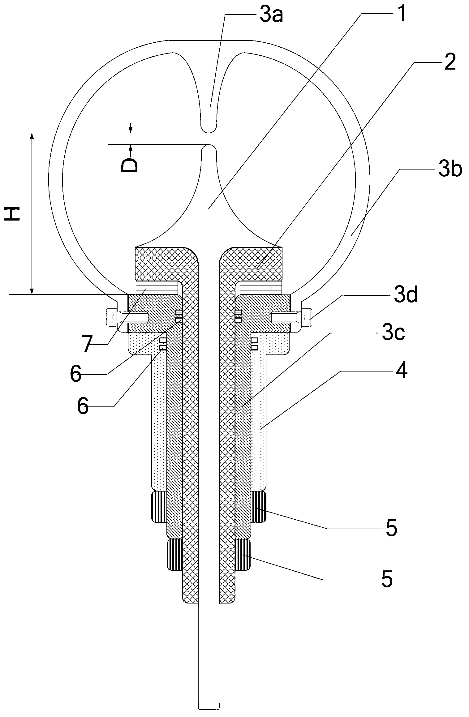
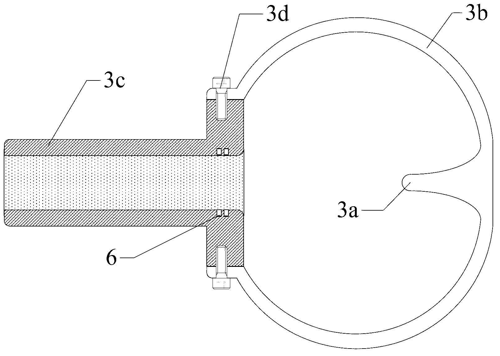
[0034] Refer to attached figure 1 , The high-power anti-shock discharge electrode in this embodiment includes an inner electrode 1 , an insulating layer 2 , an outer electrode 3 and a fixed base 4 .

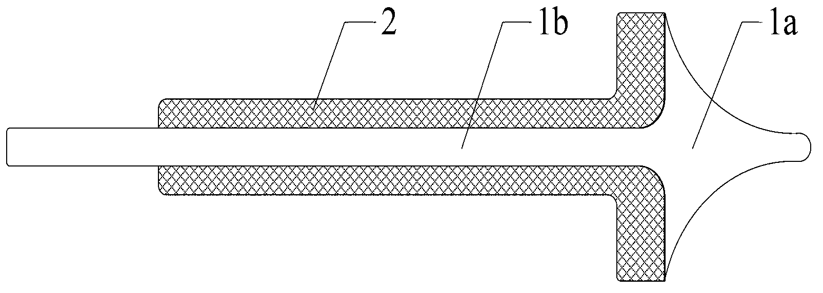
[0035] Refer to attached figure 1 And attached figure 2 , the internal electrode 1 is an integrated T-shaped internal electrode, and the integrated T-shaped internal electrode is composed of a T-shaped internal discharge contact 1a and an internal electrode body 1b. The T-shaped internal discharge contact is gradually connected from the top of the contact to the root of the contact. The radius of the cross section is increased, and one end of the internal electrode main body 1b is fixedly connected to the center of the root of the T-shaped internal discharge contact 1a by welding or casting. The T-shaped internal discharge contact 1a is used as one pole of the discharge electrode, and a mat...


PUM


Abstract

The invention provides a high-power impact-resistant discharge electrode which comprises an inner electrode, an insulating layer, an outer electrode and a fixed base. The inner electrode is an integrated T-shaped inner electrode composed of a T-shaped inner discharge contact and an inner electrode body. The outer electrode comprises an outer discharge contact, an arc-shaped cross support and an outer electrode body. The inner discharge contact is designed in the T-shaped structure, so that impact force is discomposed and distributed to the T-shaped end and side impact resistance strength of the inner discharge contact is increased greatly. The T-shaped structure of the inner discharge contact provides the discharge contact with greatly increased radiating area and mechanical strength, and the discharge electrode is protected from damage caused by untimely radiating, insufficient fatigue strength and the like during high repetition frequency discharging. The T-shaped inner discharge contact and the inner electrode body form the integrated structure for the inner electrode, so that current tolerance, mechanical strength and radiating speed are increased and the loss is low. The high-power impact-resistant discharge electrode is especially applicable to high repetition frequency discharging under high power and high current.

Description

technical field [0001] The invention relates to a discharge electrode, in particular to a high-power impact-resistant discharge electrode. Background technique [0002] The underwater plasma sound source is a pulsed sound source that uses the "hydroelectric effect" to generate underwater shock waves. It has a series of advantages such as high emission sound power, narrow pulse, and wide frequency band. It is widely used in the fields of in vitro gravel and pipeline descaling, food disinfection and sewage treatment, marine exploration and target detection. The so-called hydroelectric effect refers to the phenomenon that when a high-voltage discharge is performed in a liquid, extremely high pressure is generated in the discharge area. The underwater plasma sound source system mainly includes a charging system, an energy storage system, a trigger system, and a discharge electrode. The discharge electrode is the core component of the electroacoustic conversion that converts the...

Claims


Application Information

Patent Timeline
Patent Type & Authority Applications(China)
IPC IPC(8): G10K15/06
Inventor 雷开卓张群飞方益喜史文涛傅增祥张勇屈健康许晖
Owner NORTHWESTERN POLYTECHNICAL UNIV
Why Eureka
Try Eureka