Over-current over-voltage protective element and manufacture method thereof

A technology of overcurrent and overvoltage protection and components, which is applied in the direction of fuse manufacturing, electrical components, emergency protection devices, etc., can solve problems such as non-ideal protection methods, and achieve good heat insulation effect

Active Publication Date: 2015-07-01
NANJING SART SCI & TECH DEV
View PDF6 Cites 0 Cited by
  • Summary
  • Abstract
  • Description
  • Claims
  • Application Information

AI Technical Summary

Problems solved by technology

[0004] As described in patent CN102362328A, it mainly improves the absorption of low-melting point alloys after melting by adopting a radial solder paste layer, while in patent CN102468645A, it mainly improves the absorption of low-melting point alloys through bridging structures. However, for the current Today, with the development of protection components towards light, thin, short and small, it is obviously not an ideal protection method

Method used


Image

  • Over-current over-voltage protective element and manufacture method thereof
  • Over-current over-voltage protective element and manufacture method thereof
  • Over-current over-voltage protective element and manufacture method thereof

Examples


Embodiment Construction

[0055]The present invention will be described in further detail below in conjunction with the accompanying drawings.

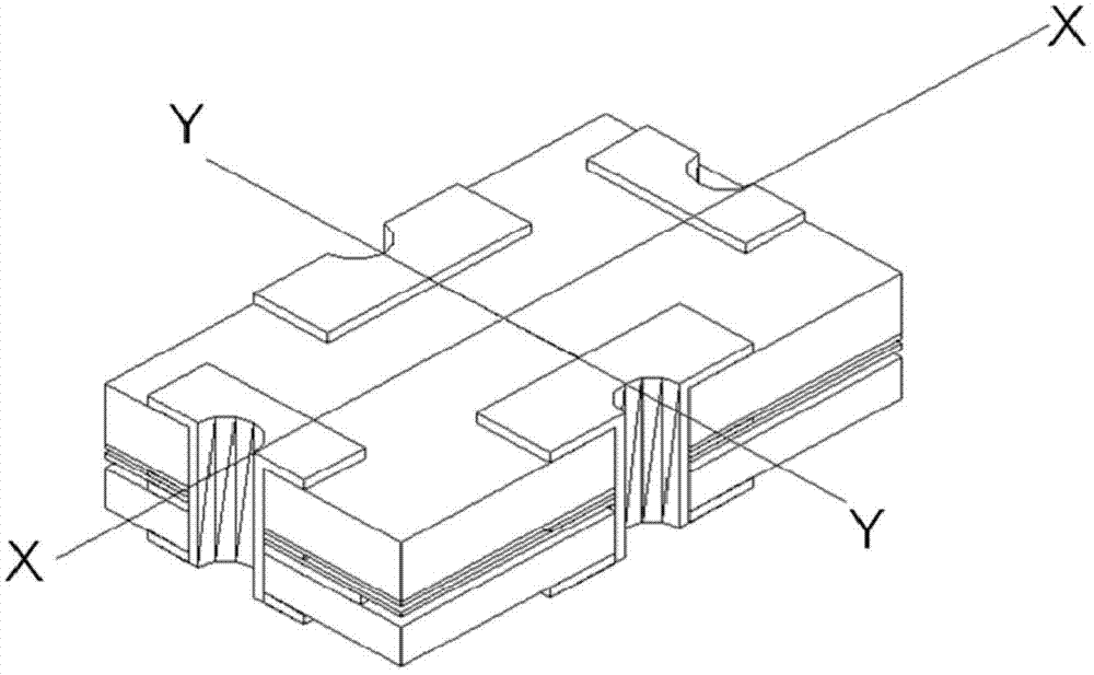
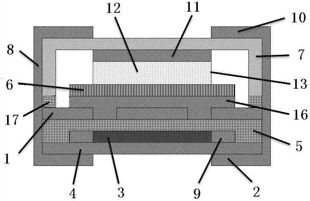
[0056] An overcurrent and overvoltage protection element according to the present invention includes a bearing plate, a melt, an upper cover plate 7 and an end electrode 8:

[0057] The carrier plate includes a middle electrode 1, a lower electrode 2, a resistance layer 3, a first insulating layer 4, and a second insulating layer 5. The middle electrode 1 is divided into at least three isolated regions, and between the middle electrode 1 and the lower electrode 2 A resistive layer 3 and a resistive electrode 9 are provided, a first insulating layer 4 is provided between the lower electrode 2 and the resistive layer 3, and a second insulating layer 5 is provided between the middle electrode 1 and the resistive layer 3;

[0058] The melt covers the middle electrode 1, so that the isolated regions of the middle electrodes 1 form an electrical connection;

[0059...


PUM


Abstract

The invention discloses an over-current over-voltage protective element and a manufacture method thereof. The over-current over-voltage protective element comprises a bearing plate, a fuse, an upper cover plate and end electrodes. A middle electrode of the bearing plate is divided into at least three isolated areas. The fuse covers the middle electrode so that the mutually isolated areas of the middle electrode are electrically connected. The upper cover plate is in a channel structure open to the bearing plate, and an open end of the upper cover plate is adhered with the bearing plate to form a cavity. The end electrodes are disposed on two sides of the bearing plate and the upper cover plate so that an upper electrode, the middle electrode and a lower electrode are electrically connected. The over-current over-voltage protective element made of high-temperature-resistant polymer material has unaffected heat resistance and is also well heat-insulating. The fuse is directly connected with the electrodes by vacuum sputtering, vacuum evaporation or plating, and drifting of the fuse caused by partial melting of the melt after being heated is avoided. A gap is added above the fuse, so that the melt fuse can be well absorbed by the gap and no tin arch occurs.

Description

technical field [0001] The invention belongs to the field of overcurrent and overvoltage protection components, and in particular relates to a structure and a manufacturing method for the overcurrent and overvoltage protection components. Background technique [0002] The protection element mounted on the secondary battery needs to have the overcurrent and overvoltage protection function. The existing overcurrent and overvoltage protection element is equipped with a heating element next to the low-temperature melt. When the current is too large, the low-temperature melt fuses due to its own heating, and the circuit is disconnected; in the second case, when the charging voltage of the battery is too high, the battery itself releases current through the heating element, causing the heating element to generate heat, and the heat emitted by the heating element reaches The melting point of the low-temperature melt makes the low-temperature melt connected to the electrodes melt an...

Claims


Application Information

Patent Timeline
Patent Type & Authority Patents(China)
IPC IPC(8): H01H85/041H01H69/02
Inventor 南式荣杨漫雪唐彬
Owner NANJING SART SCI & TECH DEV
Why Eureka
Try Eureka