Electric vehicle power system and control method thereof
A technology for electric vehicles and power systems, applied in circuits, electrical components, secondary batteries, etc., can solve the problems affecting the performance of electric vehicles and the rapid decline of battery capacity, and achieve the effect of improving performance and charging and discharging performance.
- Summary
- Abstract
- Description
- Claims
- Application Information
AI Technical Summary
Problems solved by technology
Method used
Image

Examples
specific Embodiment approach 1
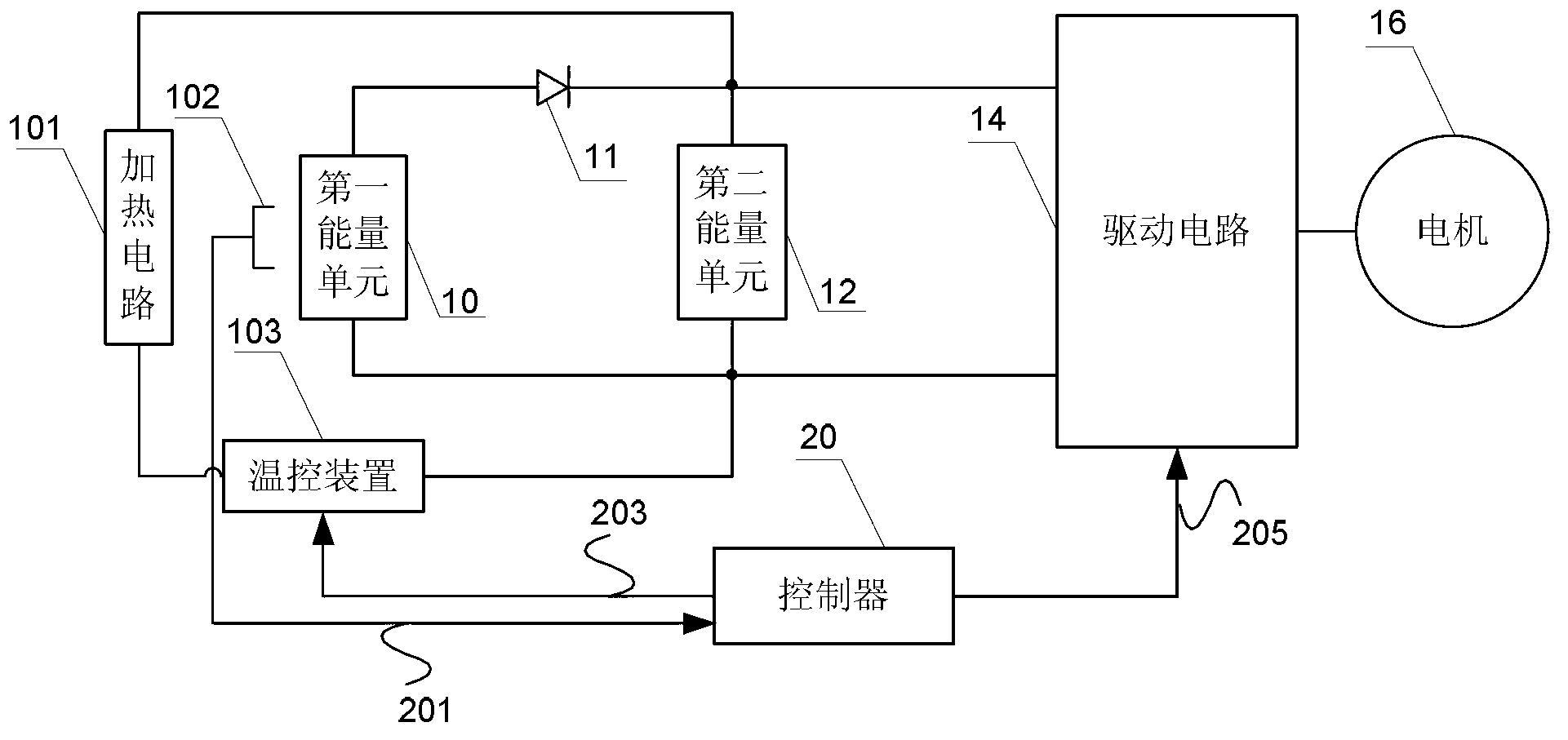
[0027] Specific implementation mode one: the following combination figure 1 Describe this embodiment, the electric vehicle power system described in this embodiment, it comprises first energy unit 10, diode 11, second energy unit 12, driving circuit 14, motor 16 and controller 20, it also comprises heating circuit 101, Temperature detection device 102 and temperature control device 103;
[0028] The first electrical signal output end of the first energy unit 10 is connected to the anode of the diode 11, the cathode of the diode 11 is connected to the first electrical signal output end of the second energy unit 12, and the first electrical signal output end of the second energy unit 12 is connected to the driver The first electrical signal input end of the circuit 14, the second electrical signal output end of the first energy unit 10 and the second electrical signal output end of the second energy unit 12 are simultaneously connected to the second electrical signal input end o...
specific Embodiment approach 2
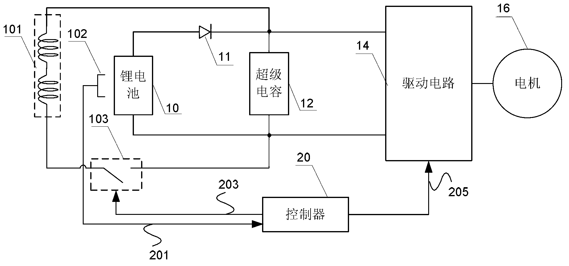
[0041] Specific implementation mode two: the following combination figure 2 This embodiment will be described. This embodiment will further describe Embodiment 1. The first energy unit 10 is a lithium battery or a lithium battery pack, and the second energy unit 12 is a supercapacitor or a supercapacitor pack.
[0042] In this embodiment, the second energy unit 12 adopts a supercapacitor or a supercapacitor bank, and the controller 20 controls the bidirectional flow of energy between the second energy unit 12 and the motor 16 . Specifically, when the electric vehicle is working in acceleration or uphill mode, the motor 16 is working in an electric state, and the energy in the power system of the electric vehicle flows from the first energy unit 10 and the second energy unit 12 to the motor 16 . When the electric vehicle works in deceleration or downhill mode, the motor 16 works in a braking state, and the energy of the power system of the electric vehicle flows from the motor 1...
specific Embodiment approach 3
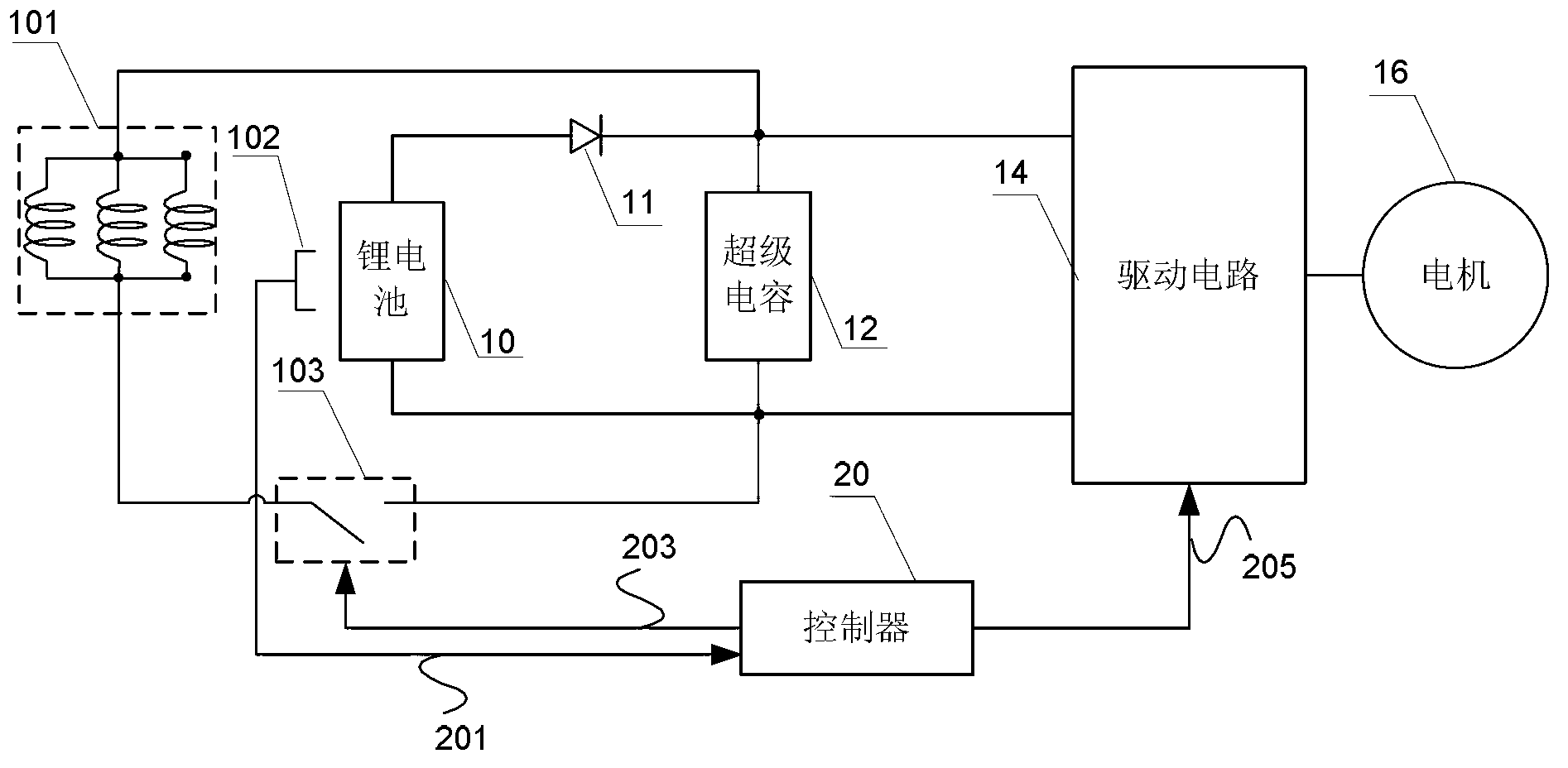
[0043] Specific implementation mode three: the following combination figure 2 This embodiment will be described. This embodiment will further describe Embodiment 1. The temperature control device 103 is a switch device, and the temperature control signal 203 is a switch signal.
[0044] In this embodiment, the switching device 103 may include but not limited to the following devices: a contactor, a power switching device and any other suitable components.
PUM
 Abstract
Description
Claims
Application Information
 - Generate Ideas
- Intellectual Property
- Life Sciences
- Materials
- Tech Scout
- Unparalleled Data Quality
- Higher Quality Content
- 60% Fewer Hallucinations
Browse by: Latest US Patents, China's latest patents, Technical Efficacy Thesaurus, Application Domain, Technology Topic, Popular Technical Reports.
© 2025 PatSnap. All rights reserved.Legal|Privacy policy|Modern Slavery Act Transparency Statement|Sitemap|About US| Contact US: help@patsnap.com