Magnetizing inrush current suppression device

A suppression device and surge current technology, applied in circuit devices, emergency protection circuit devices, emergency protection circuit devices for limiting overcurrent/overvoltage, etc., can solve problems such as waveform distortion and circuit voltage reduction

Active Publication Date: 2013-08-07
KODENSYA
View PDF11 Cites 7 Cited by
  • Summary
  • Abstract
  • Description
  • Claims
  • Application Information

AI Technical Summary

Problems solved by technology

[0002] It is known that a three-phase transformer in a state of being separated from the power system is connected to the power system by turning on the circuit breaker

Method used


Image

  • Magnetizing inrush current suppression device
  • Magnetizing inrush current suppression device
  • Magnetizing inrush current suppression device

Examples


no. 1 approach )

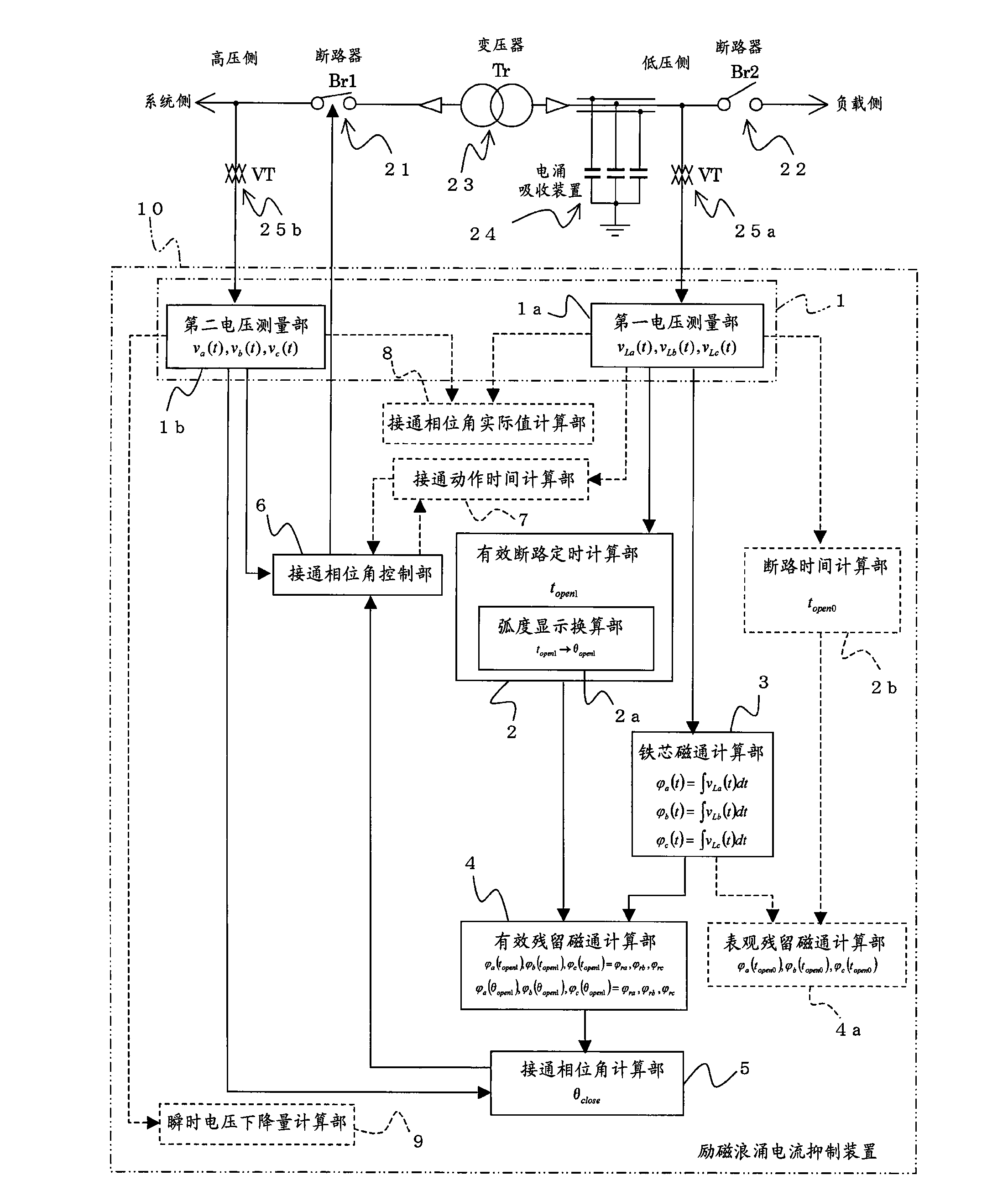
[0028] When describing the excitation surge current suppressing device 10 of this embodiment, use figure 1 and figure 2 Describe the three-phase transformer (hereinafter referred to as transformer 23) that is operating in the no-load excitation state (load side circuit breaker 22: off state, system side circuit breaker 21: on state) when the system side circuit breaker 21 is turned off. Residual magnetic flux remaining in the iron core of the transformer 23 when disconnected from the power system.

[0029] In the following description, the subscripts a, b, and c of the voltage v, the current i, and the magnetic flux φ indicate the values ​​of the a-phase, b-phase, or c-phase.

[0030] When the operating transformer 23 is disconnected from the power system, first, the load-side circuit breaker 22 on the secondary side (low voltage side, load side) of the transformer 23 is opened, and the transformer 23 enters a no-load excitation state.

[0031] In this stage (no-load excita...

no. 2 approach )

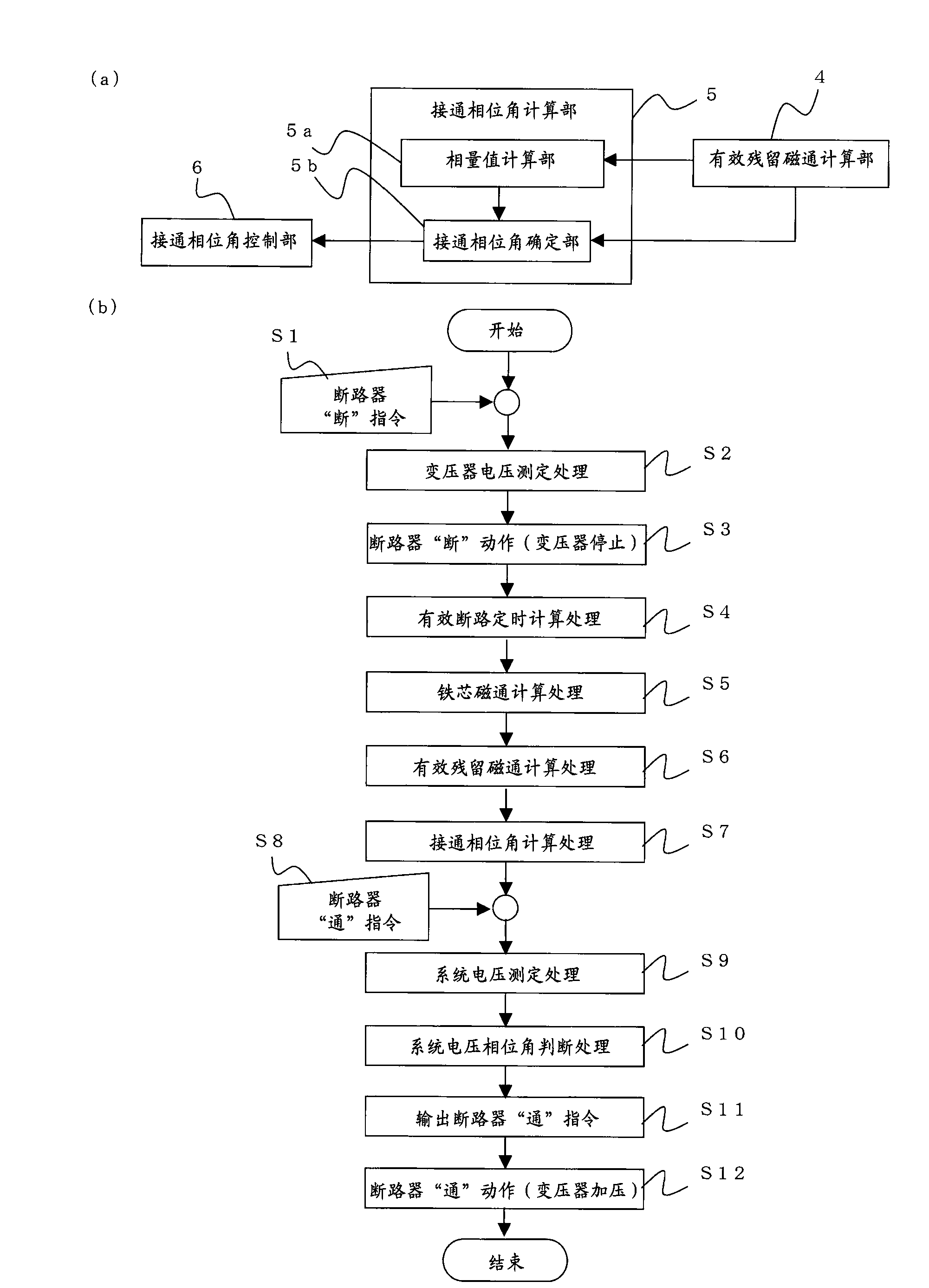
[0141] Figure 5 (a) is a block diagram showing a schematic configuration of a closing phase angle calculation unit of the second embodiment, Figure 5 (b) is expressed by Figure 5 (a) shown in the ON phase angle calculation section performed by image 3 A flow chart of the detailed processing of step S7 is shown. exist Figure 5 in, with Figure 1~Figure 4 The same symbols denote the same or corresponding parts, and descriptions thereof are omitted.

[0142] The closing phase angle calculation unit 5 of the present embodiment is based on the effective residual magnetic flux (φ ra , φ rb , φ rc ) magnitude (absolute value) and polarity, calculate the turn-on phase angle θ for the system side circuit breaker 21 close .

[0143] Also, turn on the phase angle θ close is the following phase angle, that is, at the system voltage (v a (t), v b (t), v c (t)) The initial field magnetic flux (φ a (θ close ), φ b (θ close ), φ c (θ close )) and the effective residual...

no. 3 approach )

[0176] Figure 6 (a) is a block diagram showing a schematic configuration of the closing phase angle calculation unit of the third embodiment. exist Figure 6 (a), with Figure 1~Figure 5 The same symbols denote the same or corresponding parts, and descriptions thereof are omitted.

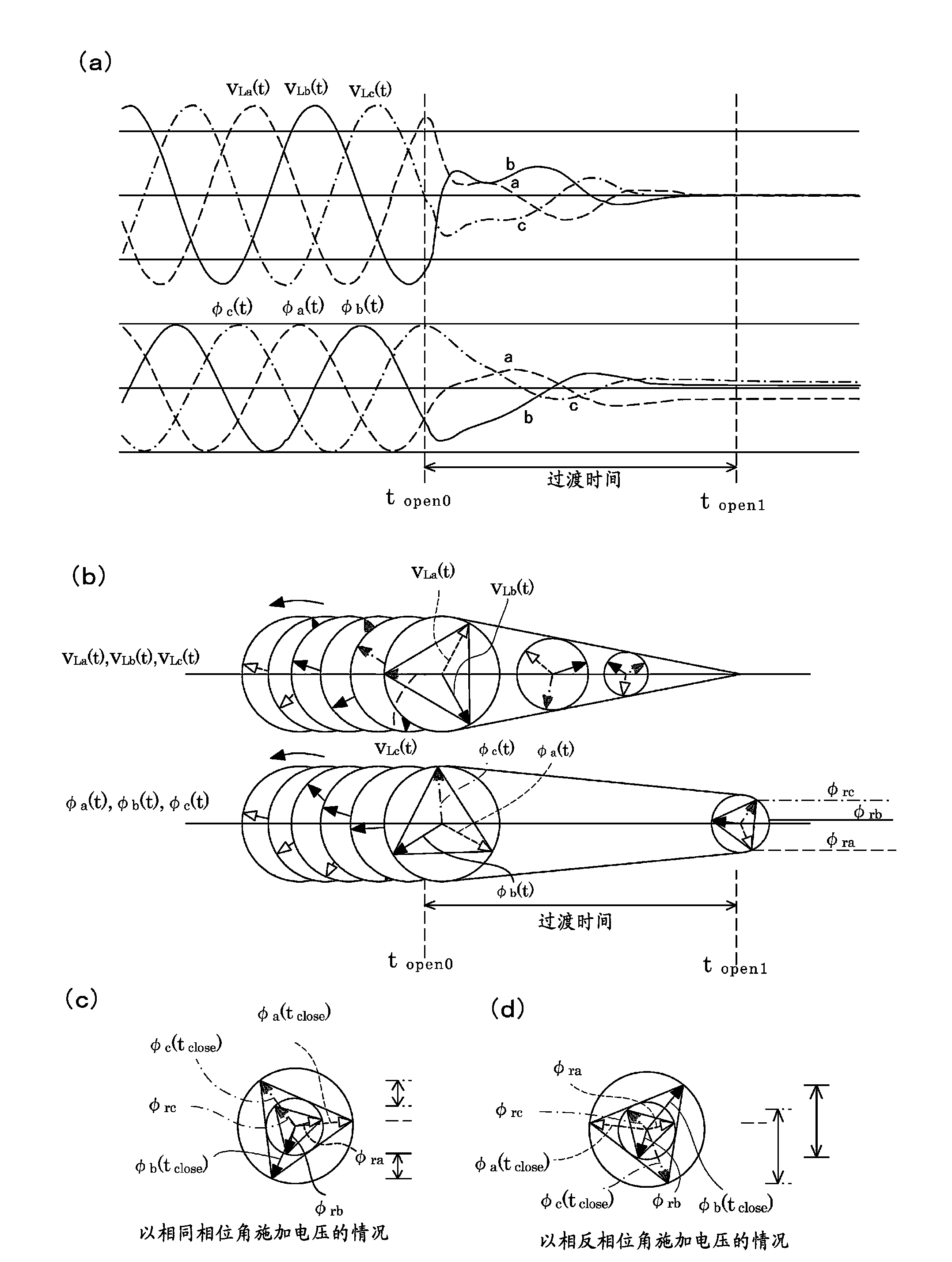
[0177] The closing phase angle calculation unit 5 of the present embodiment includes: a reference phase determination unit 5c for determining a phase as a reference in determining the closing phase angle; and a closing phase angle candidate calculation unit 5d for determining two candidates for the closing phase angle. ; Turn on the phase angle determination part 5e, and select the optimal phase angle among the candidates of the turn-on phase angle (such as figure 2 (c)), discarding the worst phase angle (e.g. figure 2 (d) case).

[0178] The effective residual magnetic flux ((φ a (t open1 ), φ b (t open1 ), φ c (t open1 )), or (φ a (θ open1 ), φ b (θ open1 ), φ c (θ open1 ))) T...


PUM


Abstract

Provided is a magnetizing inrush current suppression device that is capable of accurately computing residual fluxes of a three-phase transformer and suppressing a magnetizing inrush current. The magnetizing inrush current suppression device (10) is equipped with: a voltage measurement unit (1) for measuring respective phase voltages of the transformer (23) and system voltages of the respective phases; an effective opening timing computation unit (2) for computing effective opening timing at which instantaneous values of the phase voltages of the three phases all converge to a value of zero; a core flux computation unit (3) for computing fluxes of the respective phases of the core of the transformer (23) by means of integration of the respective phase voltages; an effective residual flux computation unit (4) that takes, among the fluxes of the respective phases, the fluxes of the respective phases obtained at the effective opening point as effective residual fluxes in order to compute effective residual fluxes of the respective phases; a closing phase angle computation unit (5) for computing a closing phase angle for a system-side breaker (21) on the basis of the effective residual fluxes of the respective phases; and a closing phase angle control unit (6) for closing the system-side breaker (21) on the basis of the system voltages of the respective phases and the closing phase angle.

Description

technical field [0001] The present invention relates to an excitation surge current suppressing device for controlling a circuit breaker (hereinafter referred to as a system side circuit breaker) connected between a three-phase transformer and a power supply of a power system (hereinafter referred to as a system power supply), in particular to It is an excitation surge current suppression device that performs effective on-on control of the system side circuit breaker for the purpose of suppressing the excitation surge current generated when the three-phase transformer is integrated into the power system. Background technique [0002] It is known that a three-phase transformer in a state of being separated from the power system is connected to the power system by turning on the circuit breaker on the system side, and an excessive excitation surge current flows, causing voltage drops and waveforms in the surrounding circuits. Distortion and other bad effects. [0003] In addi...

Claims


Application Information

Patent Timeline
IPC IPC(8): H01H33/59H02H7/04H02J3/00
CPCH02H7/0455H02J3/00H02H7/04H01H33/59H01H9/563H02H9/002
Inventor 甲斐稔康长谷良秀
Owner KODENSYA
Why Eureka
Try Eureka