Self-stabilization artificial vertebral body

A self-stabilizing, vertebral body technology, applied in the direction of prosthesis, fixator, internal fixator, etc., can solve the problems of poor mechanical environment of screws, increased probability of nail breakage, insufficient support strength, etc.

Inactive Publication Date: 2013-08-14
BEIJING AKEC MEDICAL
View PDF8 Cites 8 Cited by
  • Summary
  • Abstract
  • Description
  • Claims
  • Application Information

AI Technical Summary

Problems solved by technology

However, in clinical application and a series of biomechanical tests, it has been shown that there are still some problems to be solved in some aspects of the traditional artificial vertebral body, especially the immediate lack of stability of the artificial vertebral body after surgery, and the early Low bonding strength, easy to cause implant displacement or even prolapse
In addition, because the artificial vertebral body is made of solid materials, in order to leave enough holes for artificial vertebral bone grafting, the effective support area of ​​the upper and lower endplates of the artificial vertebral body is often reduced, resulting in insufficient support, and the artificial vertebral body gradually sinks into the upper and lower endplates. The bone in the vertebral body eventually loses the ideal support height
In order to reduce the impact of the above problems, people have to implement an anterior or posterior nail-plate or nail-rod fixation system while implanting the artificial vertebral body in order to provide stability in the early stage and during the fusion period, which in turn brings about additional problems , such as the increase in surgical costs, the mechanical environment of the screws in the internal fixation system is quite harsh, which increases the probability of screw breakage, the nail plate or screw rod fixation system protrudes or suspends beyond the surface of the physiological vertebral body, which adversely affects the surrounding tissues, etc.

Method used


Image

  • Self-stabilization artificial vertebral body
  • Self-stabilization artificial vertebral body
  • Self-stabilization artificial vertebral body

Examples


Embodiment Construction

[0036] The present invention will be described in detail below with reference to the accompanying drawings and examples.

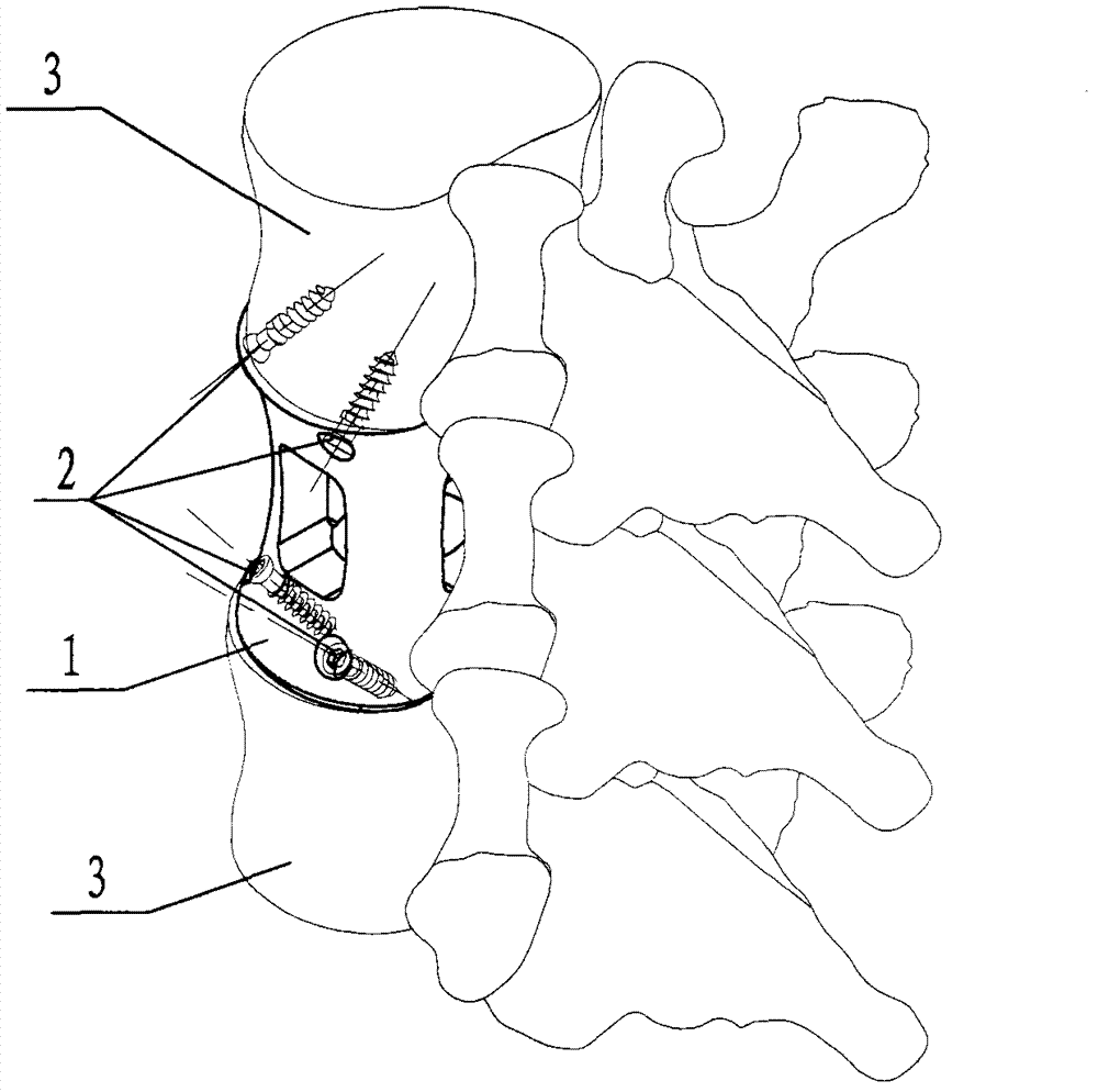
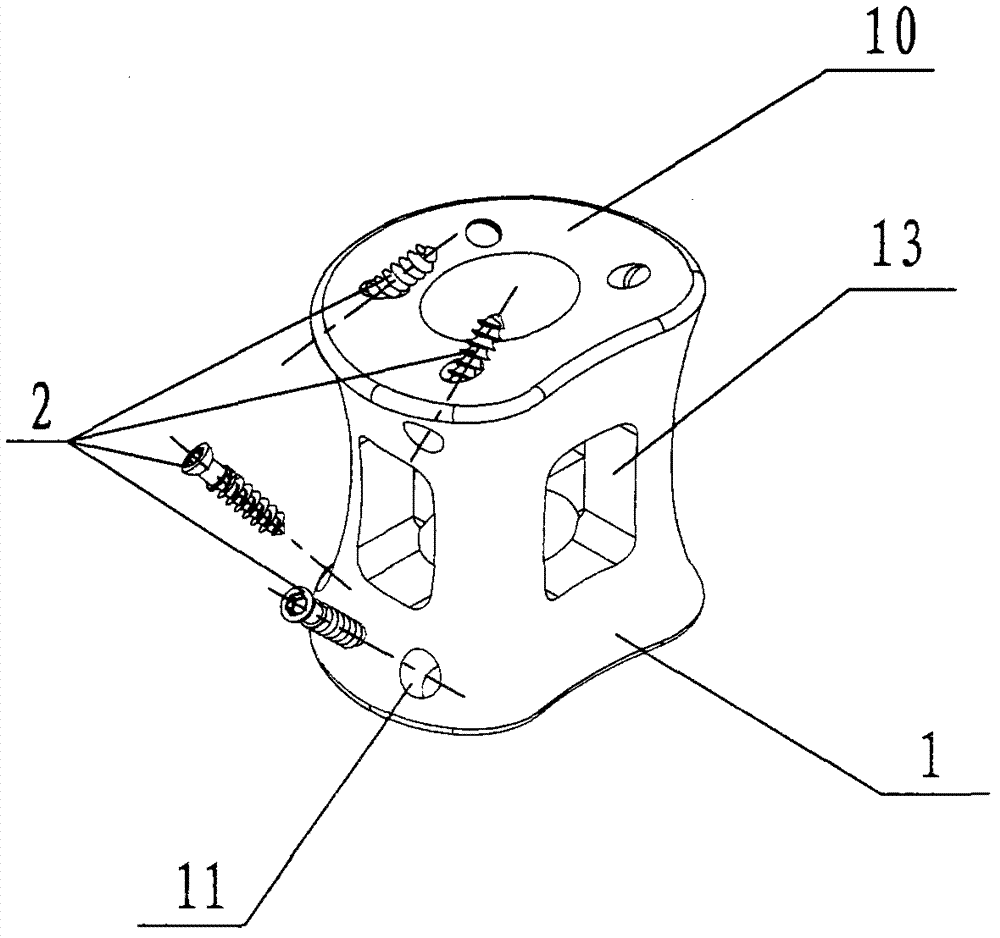
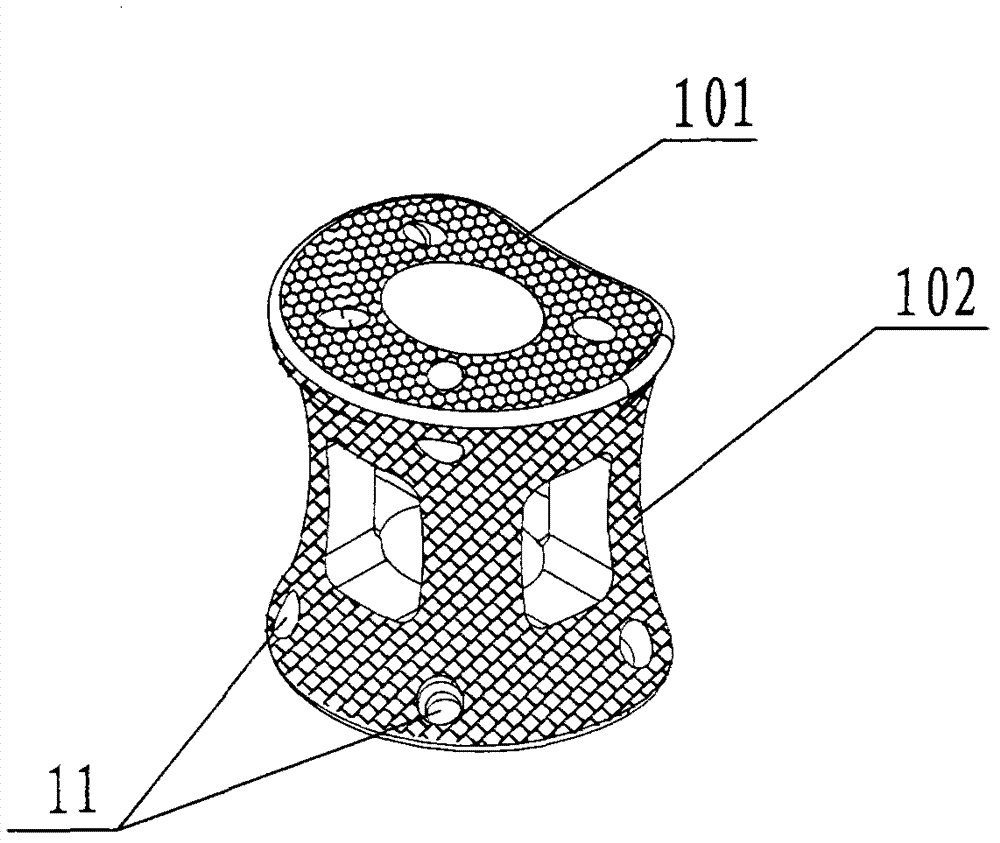
[0037] like figure 1 , figure 2 The shown self-stabilizing artificial vertebral body according to the present invention is set at the space position left by the removed host vertebral body that cannot normally perform its own function due to tumor, trauma, or congenital disease. The stabilized artificial vertebral body includes a vertebral body body 1 and a vertebral body fixation screw 2, wherein the vertebral body body 1 is used to replace the resected or missing segment of the host vertebral body to restore and reconstruct the physiological height of the spine and will be formed in the future. Bone fusion between adjacent healthy vertebral bodies 3, vertebral body fixing screws 2 pass through the vertebral body fixing screw holes 11 to connect and fix the vertebral body main body 1 with the upper and lower adjacent healthy vertebral body 3 segments, a...


PUM


Abstract

The invention relates to a self-stabilization artificial vertebral body which is used for being inserted to replace resected or deleted parasitic vertebral body sections. The self-stabilization artificial vertebral body comprises a vertebral body main body and vertebral body fixing screws. An integration surface of the vertebral body main body and a vertebral body is a microcellular structure which is beneficial to ingrowth of bone cells. In an operation, the vertebral body main body with the suitable height is installed into the position with a damaged parasitic vertebral body section taken out and the vertebral body main body is fixed with an adjacent upper main healthy vertebral body and an adjacent lower main healthy vertebral body through the vertebral body fixing screws by penetrating through vertebral body fixing screw holes. The self-stabilization artificial vertebral body has the advantages of being good in instance stability after the operation and good in synostosis to effectively resist to subsidence, enabling the height of the replaced vertebral body to be continuously kept and being free of incisure after the operation and simple and reliable in operation.

Description

technical field [0001] The invention relates to the field of orthopedic implants, and more particularly relates to a self-stabilizing artificial vertebral body which is used for replacing damaged spinal vertebral bodies, has good immediate postoperative stability and can realize long-term bone fusion. Background technique [0002] In the treatment of human spinal diseases, spinal tumors, tuberculosis and severe fractures often cause vertebral body damage, which may lead to spinal cord nerve damage, so vertebral body resection has to be performed. After vertebral body resection, the spine needs to rebuild its stability. The emergence of vertebral body replacement provides an ideal method for the treatment of such diseases. Since the first report of vertebral body tumor resection and prosthetic replacement in the late 1960s, artificial vertebral bodies have been widely used clinically as a kind of effective vertebral body substitutes. However, in clinical application and a se...

Claims


Application Information

Patent Timeline
Patent Type & Authority Applications(China)
IPC IPC(8): A61F2/44A61B17/70
CPCA61F2/44A61F2002/30001
Inventor 刘忠军
Owner BEIJING AKEC MEDICAL
Why Eureka
Try Eureka