Brake fluid replacing device and working method thereof

A technology of brake fluid and changer, which is applied in vehicle maintenance, vehicle maintenance/repair, transportation and packaging, etc. It can solve the problem of brake pipeline damage, brake master cylinder, brake wheel cylinder, high flow rate of brake fluid, The flow is difficult to control and other problems, to achieve the effect of ensuring braking safety, saving manpower and material resources, and improving work efficiency

Inactive Publication Date: 2013-08-14
JIANGSU UNIVERSITY OF TECHNOLOGY
View PDF6 Cites 5 Cited by
  • Summary
  • Abstract
  • Description
  • Claims
  • Application Information

AI Technical Summary

Problems solved by technology

However, the material of the brake fluid storage tank on the car is generally plastic, which often deforms and even leaks under high pressure; at the same time, the flow rate of the new brake fluid pressed into the brake fluid storage tank is difficult to control , there may be a phenomenon that the flow rate of the brake fluid is high and the flow rate of the brake fluid port is low, resulting in excessive hydraulic pressure in the brake pipeline and damage to the brake master cylinder and each brake wheel cylinder.

Method used


Image

  • Brake fluid replacing device and working method thereof
  • Brake fluid replacing device and working method thereof
  • Brake fluid replacing device and working method thereof

Examples


Embodiment 1)

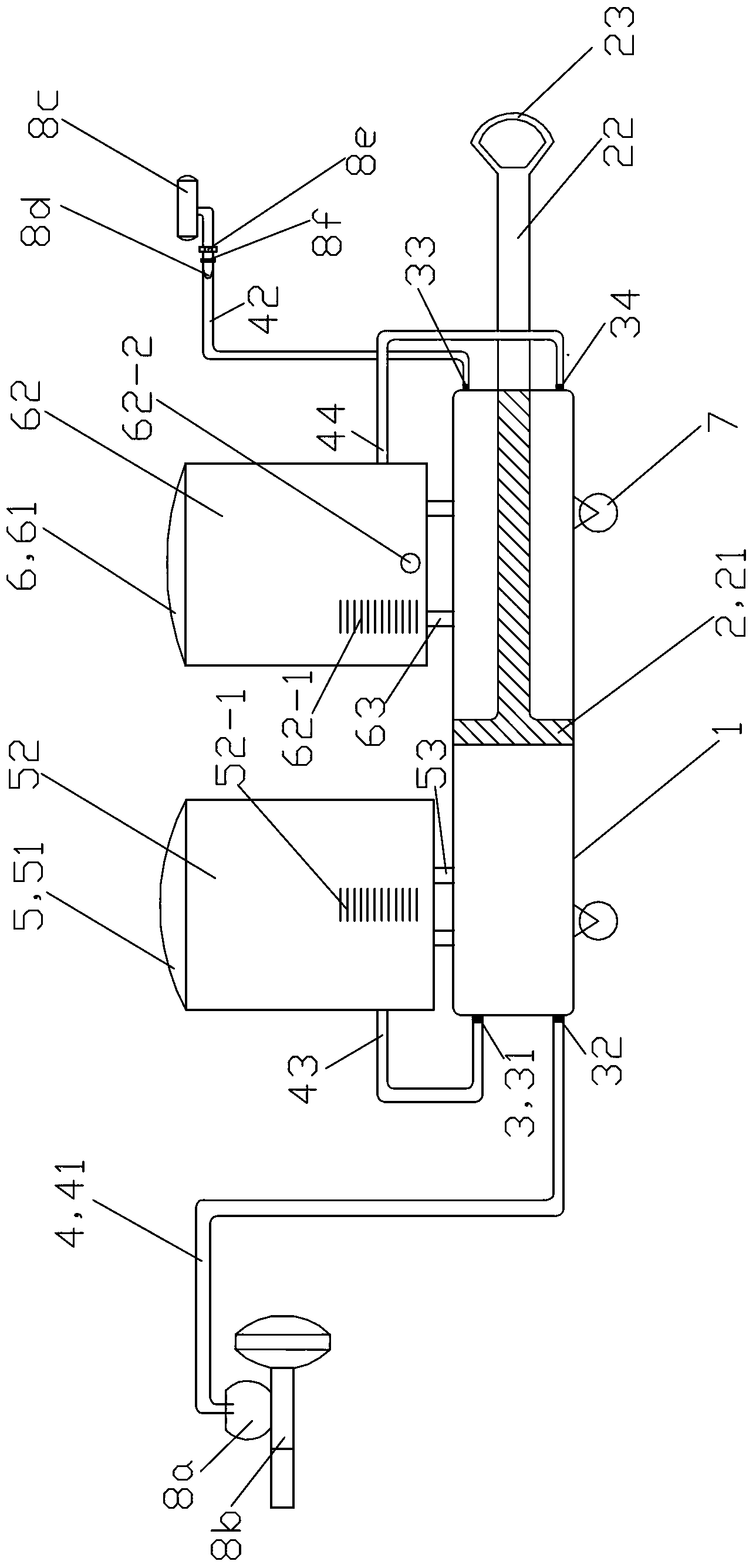
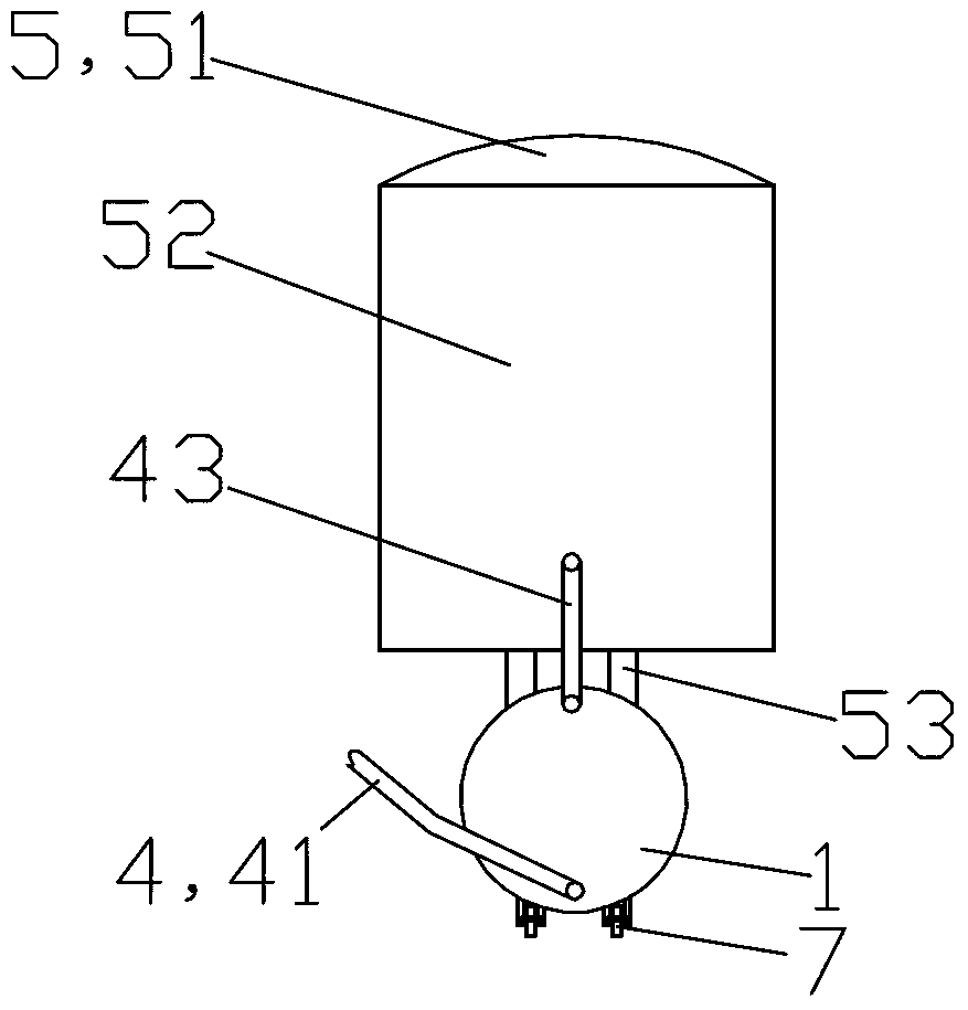
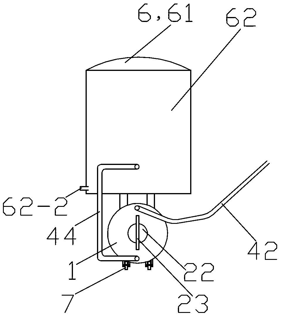
[0030] See Figure 1 to Figure 3 , The brake fluid changer of this embodiment is mainly composed of a piston cylinder 1, a piston assembly 2, a one-way valve assembly 3, a connecting pipe assembly 4, a brake fluid bucket 5, a waste fluid bucket 6 and a roller 7.

[0031] The piston cylinder body 1 is a steel part. The piston cylinder 1 is integrally formed by a circular left side plate, a circular right side plate and a hollow cylinder in the middle. The piston cylinder body 1 is arranged left and right. The upper end and the lower end of the left side plate of the piston cylinder 1 are respectively provided with a left and right through hole as a valve mounting hole, and the two through holes are located on the front and rear central axis of the left side plate of the piston cylinder 1 . The upper end and the lower end of the right side plate of the piston cylinder 1 are also respectively provided with a left and right through hole as a valve installation hole, and the two ...


PUM


Abstract

The invention provides a brake fluid replacing device. The brake fluid replacing device comprises a piston cylinder body, a piston assembly, a one-way valve assembly, a communicating pipe assembly, a brake fluid barrel, a waste liquid barrel and an idler wheel, wherein the piston cylinder body uses the one-way valve assembly and the communicating pipe assembly through a piston, sucks new hydraulic drive fluid in the brake fluid barrel, and pushes the new hydraulic drive fluid into a brake fluid storage pot of a car, and simultaneously, the piston cylinder body achieves replacement of waste brake fluid by sucking the waste brake fluid in a car brake wheel cylinder through the piston and pushing the waste brake fluid into the waste liquid barrel. The brake fluid barrel and the waste liquid barrel are fixedly installed at the upper end of the piston cylinder body through supports, and the idler wheel is fixedly installed below the piston cylinder body. A working method of the brake fluid replacing device is a negative pressure suction method. The brake fluid replacing device is simple in structure and low in cost, effectively guarantees that no air enters into a brake pipeline system during the brake fluid replacing process, and therefore can not reduce brake performance of the car, facilitates judging whether a brake pipeline leaks or not, is convenient to replace and operate, and saves manpower and material resources.

Description

technical field [0001] The invention relates to an automobile brake fluid replacement device and a replacement method, in particular to an automobile brake fluid changer and a working method thereof. Background technique [0002] Automobile brake fluid is generally replaced every 2 years. During the brake fluid replacement process, air should not enter the brake pipeline to prevent the braking performance from being reduced. At present, the commonly used brake fluid replacement method in automobile 4S shops is: first open the cover of the brake fluid storage tank, one person sits in the driver's seat, lifts the car with a lift, and the other person is outside the car, and uses a plastic One end of the hose is connected to the drain port of a certain wheel brake, and the other end is extended into the waste liquid bucket. The driver steps on the brake pedal, and the person outside the vehicle uses a tool to loosen the fastening nut of the drain port. The waste liquid flows i...

Claims


Application Information

Patent Timeline
IPC IPC(8): B60S5/00
Inventor 张焱刘成晔
Owner JIANGSU UNIVERSITY OF TECHNOLOGY
Why Eureka
Try Eureka