

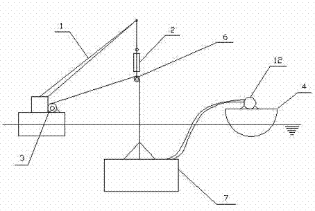
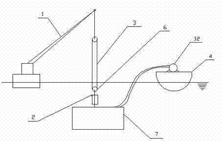
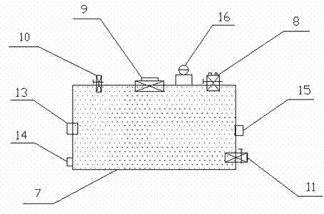
Device and method for installing deep sea submarine storage tank
An installation method and a storage tank technology, which are applied in hoisting devices, transportation and packaging, ships, etc., can solve the problems of unoptimized combination of large-scale submarine facilities, high energy consumption of compressed air, and difficulty in equipment selection, etc., and achieve structural design Easy, improve safety and reliability, save the effect of controlling the gas path
- Summary
- Abstract
- Description
- Claims
- Application Information
AI Technical Summary
Problems solved by technology
Method used
Image

Examples
Embodiment 1
[0040] Example 1: 20000 m 3 Underwater tank installation
[0041] The main body of the storage tank is made of steel, with double walls, double roofs and no bottom. The maximum capacity of the storage tank is 20000 m 3 , including fixed weight 4780t. The water depth of the target sea area is 1500m. The oil storage tank is filled with 16800 m 3 The density is 840kg / m 3 After the diesel oil and other spaces are filled with seawater, the underwater weight is 246t. It can be realized with the current heave compensator for floating cranes and drilling ships. This combination also has a certain adjustment margin.
Embodiment 2
[0042] Example 2: Installation of a 100,000m3 subsea storage tank. The storage tank is a closed combination storage tank with a designed oil storage capacity of 100,000 cubic meters and a self-weight of 18,577t including fixed counterweights. Oil storage tank filled 84000 m 3 Density 850kg / m 3 diesel, other spaces are filled with seawater. The underwater weight is 757t. This combination also has a certain adjustment margin.
Embodiment 3
[0043] Example 3: 4000 m 3 ×N (N is an integer) underwater tank group installation. The underwater storage tank unit is a closed storage tank, and the rated capacity of a single tank is 4000 m 3 , including a fixed weight of 1509t, the water depth of the target area is 300m. The oil storage tank is filled with a density of 800kg / m 3 kerosene, the underwater weight of a single unit is 85t. After the monomer is completed, the underwater operation completes the connection of each tank.
PUM
 Abstract
Description
Claims
Application Information