
Reactor for reinforcement of catalyst particle interception and microwave synergistic photocatalytic wastewater degradation

A waste water degradation and reactor technology, applied in chemical instruments and methods, light water/sewage treatment, oxidized water/sewage treatment, etc., can solve problems such as troublesome, unreliable, and overflow reactors

Inactive Publication Date: 2013-08-14
NINGBO UNIV
View PDF6 Cites 4 Cited by
  • Summary
  • Abstract
  • Description
  • Claims
  • Application Information

AI Technical Summary

Problems solved by technology

[0046] Based on the structure of the CN102260003A scheme, during its operation, the water pump that fills the reactor cavity with waste water cannot judge whether the water level inside the reactor is high or low, and the operator can only rely on experience or visual inspection to turn off the water pump that fills the waste water in time Motor, if the experience is wrong or the visual response is not timely enough, it is easy to overflow the reactor due to excessive filling of waste water, which will cause unnecessary trouble; The membrane module pumps water outward. Without knowing the water level inside the reactor, the timing of shutting down the pump can only be judged based on experience or visual inspection. This operation is obviously unreliable, and it is very easy to make mistakes due to experience or visual inspection. If the response is not timely, the water pump cannot be shut down in time, and this kind of dry pumping and idling can easily cause the motor of the water pump to burn out. This problem cannot be ignored. This is the fourteenth problem.

Method used


Image

  • Reactor for reinforcement of catalyst particle interception and microwave synergistic photocatalytic wastewater degradation

Examples


Embodiment Construction

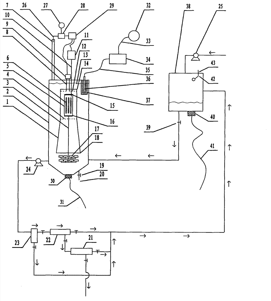
[0123] exist figure 1In the shown embodiment of the present case, the main component of the reactor is a hollow container 2, and the outline of the container 2 is in the shape of a cube, a cuboid, a cylinder, an ellipse, a polygon, a sphere or an ellipsoid. Body shape, the structure of the reactor also includes a microporous aeration head 17, the label 17 only indicates the microporous aeration head individual and its shape in the legend, the number of the microporous aeration head 17 is more than one, the micropore The installation position of the aeration head 17 is in the lower area of ​​the inner cavity of the container 2, and the quartz tube 5 is installed on the inner cavity position of the container 2, and the two ends of the quartz tube 5 are equipped with seals. Plugging caps 15, 16, the two plugging caps 15, 16 respectively located at the two ends of the quartz tube 5 are provided with ventilation ports, and the electrodeless ultraviolet lamp 6 is rod-shaped, ring-sh...


PUM

PropertyMeasurementUnit
pore sizeaaaaaaaaaa
pore sizeaaaaaaaaaa
pore sizeaaaaaaaaaa

Abstract

The invention relates to a reactor for reinforcement of catalyst particle interception and microwave synergistic photocatalytic wastewater degradation, belonging to the technical field of wastewater treatment. The following problems exist in the prior related art: the catalyst intercepting link is weaker, the single-tank treatment capacity of the reactor is smaller, the repetitive operation frequency is high, the internal cyclic strength of liquid is insufficient, ozone utilization is incomplete, the degradation reaction endpoint is difficult to distinguish, catalyst agglomerates can not be dispersed in situ by strong force, and occurrence of catalyst agglomeration can not be perceived immediately. The invention aims to solve the problems once. The structure of the reactor separates and limits the microwave irradiation area, guides the ozone bubble flow to key degradation reaction areas, finely intercepts the catalyst particles with an external cascaded filter, can disperse the catalyst agglomerates in situ by strong force, simultaneously carries out ultrasonic cleaning on quartz tubes incidentally, can automatically turn off the related power supply when the degradation reaction reaches the endpoint, and can actively detect the tendency of catalyst agglomeration and carry out automatic warning.

Description

technical field [0001] The invention relates to a microwave synergistic photocatalytic wastewater degradation reactor that strengthens the interception of catalyst particles, and belongs to the technical field of CO2F wastewater treatment. Background technique [0002] Microwave photocatalytic degradation treatment technology, as an effective harmless treatment technology for industrial wastewater containing organic pollutants, has attracted much attention in recent years. [0003] Regarding the microwave photocatalytic degradation technology, as an example, refer to the Chinese patent application with publication number CN102260003A. [0004] The Chinese patent application with the publication number CN102260003A uses microwaves as the excitation source to excite the electrodeless ultraviolet lamp to emit ultraviolet rays, and irradiates the suspension mixed with photocatalyst titanium dioxide inside the liquid. The electrodeless ultraviolet lamp is shrouded and protected b...

Claims


Application Information

Patent Timeline
Patent Type & Authority Applications(China)
IPC IPC(8): C02F9/08C02F1/32C02F1/30C02F1/78C02F1/36
Inventor 李榕生王冬杰任元龙葛从辛孙杰干宁张佳斌孔祖萍
Owner NINGBO UNIV
Learn More