
Novel ultrahigh-pressure high-flow charging or filling valve

An ultra-high pressure, high flow technology, applied in the direction of sliding valves, valve details, control valves, etc., can solve the problem of increasing the size of the pressure bearing body and flange seat, increasing the annular space between the valve core and valve seat, and the pressure bearing body Solve problems such as bulky structure, achieve light structure, improve production efficiency, and solve the effect of long pouring time

Active Publication Date: 2013-08-14
GANSU LANPEC TECH +3
View PDF5 Cites 3 Cited by
  • Summary
  • Abstract
  • Description
  • Claims
  • Application Information

AI Technical Summary

Problems solved by technology

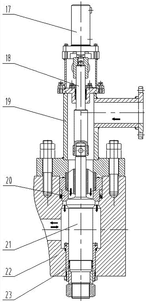
It can be seen from the schematic diagram that the cone sealing structure requires the valve core and valve seat to have extremely high machining accuracy and heat treatment process to improve wear resistance and increase the working life. Even so, the opening and closing of the valve core during the working process The frequency is relatively high. With the continuous wear between the valve core and the valve seat, the cone seal will quickly fail, so the reliability of the valve is poor and the working life is short; at the same time, in order to ensure that a large flow of liquid passes through the valve, the valve must be enlarged The annular space between the core and the valve seat increases the structure of the valve, and the external dimensions of the pressure-bearing body and the flange seat will also increase accordingly, making the entire pressure-bearing body structure bulky.
Therefore, it is necessary to develop a new type of ultra-high pressure and large flow filling (filling) valve with very high reliability, which not only solves the problem of poor reliability of the filling (filling) valve of steel pipe hydraulic testing machine under high pressure conditions, but also solves the problem of production efficiency. Low bottleneck technical problems

Method used


Image

  • Novel ultrahigh-pressure high-flow charging or filling valve
  • Novel ultrahigh-pressure high-flow charging or filling valve
  • Novel ultrahigh-pressure high-flow charging or filling valve

Examples


Embodiment Construction

[0017] The present invention and its beneficial effects will be described in further detail below with reference to the accompanying drawings.

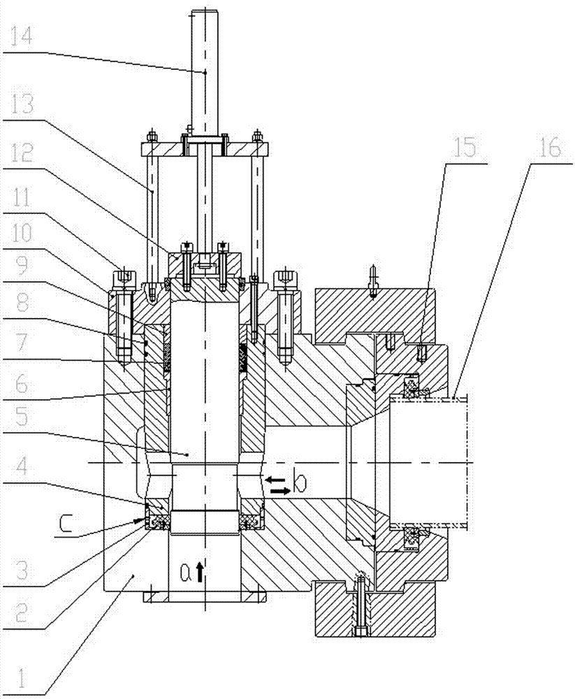
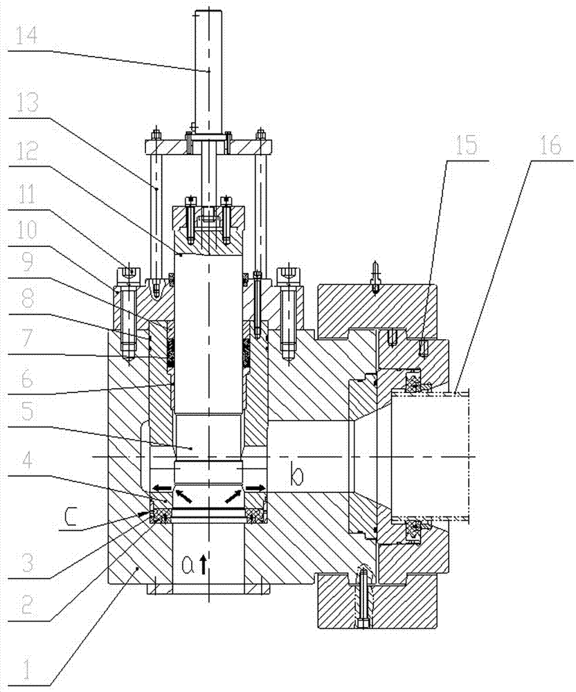
[0018] Reference Figure 1-2 , A new type of ultra-high-pressure large-flow liquid-filled or perfusion valve, mainly composed of pressure-bearing body 1, large radial gap elastic sealing ring 2, positioning ring 3, guide body 4, valve core 5, guide sleeve 6, V-shaped combined seal 7. High-pressure sealing ring 8, compression sleeve 9, high-pressure flange 10, screw 11, positioning flange 12, bracket 13, hydraulic or pneumatic cylinder 14. The radial large gap elastic sealing ring 2 adopts a high-strength polyurethane annular sealing ring and is installed in the positioning ring 3, and forms an integrated block with the guide sleeve 6, the V-shaped combined seal 7, and the pressure sleeve 9 installed in the guide body 4. Then, it is fixed in the pressure-bearing body 1 by the high-pressure flange 10, the screw 11 and the high-pressure sea...


PUM


Abstract

A novel ultrahigh-pressure high-flow charging or filling valve comprises pressure bearing body, a valve spool and a hydraulic or pneumatic cylinder connected with the upper end of the valve spool. A guider is assembled on the lower portion of the valve spool, and forms a dynamic ultrahigh-pressure seal with the lower portion of the valve spool through a locating ring mounted at the lower end of the guider and a large-radial-clearance elastic sealing ring mounted in the locating ring. The lower end face of the valve spool and a lower channel of the bearing body form a low-pressure area a after the valve spool is sealed by the large-radial-clearance elastic sealing ring; and meanwhile, the periphery of the large-radial-clearance elastic sealing ring and the inner channel of the bearing body form a high-pressure area c. The guider and the valve spool form a sliding ultrahigh-pressure seal through a pressing sleeve, a V-shaped combined sealing and a guide sleeve which are all mounted on the upper portion of the guider in sequence. By the arrangement, the problems of long low-pressure filling time of steel pipes with large diameters and service life of the charging or filling valve are solved, weight of sealing mould of ultrahigh-pressure steel pipe hydraulic pressure tester is reduced, and production efficiency of the hydraulic pressure tester is greatly improved.

Description

technical field [0001] The invention relates to the fields of mechanical equipment such as petroleum drilling, metallurgy and nuclear energy, and specifically relates to a novel ultrahigh-pressure and large-flow fluid-filling or perfusion valve used in hydraulic tests after steel pipe production or reprocessing. Background technique [0002] In recent years, as the country's demand for steel pipes has soared, the domestic steel pipe output is close to more than 70 million tons, of which nearly half of the output is used as oil steel pipes. According to the requirements of API specifications and related standards, oil steel pipes must pass through hydraulic pressure. Only after passing the test can it be put into use. Therefore, petroleum steel pipe manufacturers must be equipped with high-reliability and high-speed ultra-high pressure hydraulic testing machines to meet production capacity requirements. For the steel pipe hydraulic testing machine, the main factors affecting ...

Claims


Application Information

Patent Timeline
Patent Type & Authority Applications(China)
IPC IPC(8): F16K3/24F16K31/122F16K15/18
Inventor 李秀全张永红解庆吴利琴席浩君
Owner GANSU LANPEC TECH
Learn More