Method and system for gas pipeline leakage detection and positioning

A technology for gas pipeline and leak detection, applied in pipeline systems, gas/liquid distribution and storage, mechanical equipment, etc., can solve the problems of leak detection and positioning, low false alarm rate, time-consuming inability to continuously detect, etc., and achieve positioning accuracy High performance, high positioning accuracy and low maintenance cost

Active Publication Date: 2013-08-14
江苏溢坤医疗科技有限公司
View PDF8 Cites 16 Cited by
  • Summary
  • Abstract
  • Description
  • Claims
  • Application Information

AI Technical Summary

Problems solved by technology

In order to achieve this goal, the present invention overcomes the shortcoming that the direct detection method cannot continuously detect and takes a long time to detect, and combines the advantages of the indirect detection method that can detect in real time, online, and continuously, and finally invents this method that can provide good sensitivity and high positioning accuracy. , Leakage detection and positioning detection system with low false alarm rate and long-term uninterrupted work

Method used


Image

  • Method and system for gas pipeline leakage detection and positioning
  • Method and system for gas pipeline leakage detection and positioning
  • Method and system for gas pipeline leakage detection and positioning

Examples


Embodiment Construction

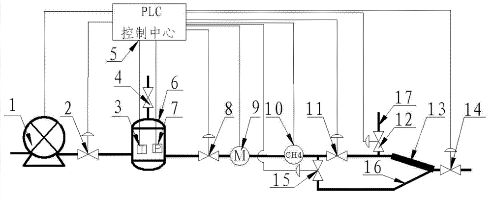
[0023] The names of the components of the detection system are as follows: figure 1 Shown: 1-vacuum pump, 2-sixth electric control valve, 3-temperature sensor, 4-manual valve, 5-PLC control center, 6-buffer tank, 7-pressure transmitter, 8-fifth electric control valve , 9-mass flowmeter, 10-combustible gas alarm, 11-third electric control valve, 12-second electric control valve, 13-test supervisor, 14-first electric control valve, 15-fourth electric control valve , 16- detection auxiliary pipe, 17- branch pipe.

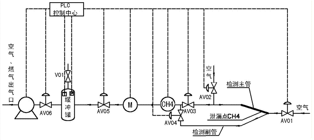
[0024] exist figure 2 The sequence of medium mixed gas flowing through each detection device is as follows: the air in the atmosphere flows through the first electric control valve (AV01) 14, passes through the detection supervisor 13, the third electric control valve (AV03) 11, and flows to the combustible gas alarm 10. If there is no leakage alarm signal from the PLC control center 5 at this time, the air flows through the mass flow meter 9, the fifth electric con...


PUM


Abstract

The invention relates to a system for gas pipeline leakage detection and positioning. The system comprises a main detection pipe, a PLC (programmatic logical controller) control center, an auxiliary pipe, a branch pipe and the like, wherein the main detection pipe is laid parallelly above a gas pipeline and is connected with a combustible gas alarm, a mass flow meter and a buffer tank. A difference value delta T of twice alarming time is recorded by the PLC control center, a mixed gas flow value recorded by the mass flow meter is converted by the PLC control center to be recorded as average velocity of mixed glass flowing in the detection pipe, and a leakage point distance value is obtained by a mathematical model formated by the control center. The system is high in sensitivity, good in positioning accuracy and low in false alarm rate, and can work uninterruptedly for a long time. A method for gas pipeline leakage detection and positioning is blank in domestic, and accelerating popularization and application of the device and the method has great significance.

Description

technical field [0001] The invention relates to the technical field of gas pipeline leakage detection, in particular to a method and system for gas pipeline leakage detection. Background technique [0002] In June 2012, the Ministry of Housing and Urban-Rural Development issued the "National Urban Gas Twelfth Five-Year Plan", which stipulates that during the "Twelfth Five-Year Plan" period, about 250,000 kilometers of new gas pipelines will be built in my country. By the end of the "Twelfth Five-Year Plan", the gas pipeline The total length reaches 600,000 kilometers. With the increase of newly built gas pipelines, the total length of pipelines continues to grow, and the coverage area of ​​pipeline networks gradually expands. Due to pipeline aging, corrosion, third-party construction damage and other reasons, gas pipeline leakage accidents often occur. According to the statistics of China Gas Association, there were 269 gas pipeline leakage accidents in 2011, resulting in 14...

Claims


Application Information

Patent Timeline
Patent Type & Authority Applications(China)
IPC IPC(8): F17D5/06
Inventor 王树立冯建国周诗岽孙少立李恩田
Owner 江苏溢坤医疗科技有限公司
Why Eureka
Try Eureka