Supercharge Your Innovation With Domain-Expert AI Agents!

Fuel injection assembly for use in turbine engines and method of assembling same

A turbine engine and fuel injection technology, applied in the direction of combustion methods, combustion chambers, combustion equipment, etc., can solve the problems of increased wear of the burner and associated components, shortening the service life of the combustion system, etc.

Inactive Publication Date: 2013-08-14
GENERAL ELECTRIC CO
View PDF7 Cites 2 Cited by
  • Summary
  • Abstract
  • Description
  • Claims
  • Application Information

AI Technical Summary

Problems solved by technology

Additionally, vibrations introduced into the combustion system may increase wear on the combustor and associated components and / or may shorten the useful life of the combustion system

Method used


Image

  • Fuel injection assembly for use in turbine engines and method of assembling same
  • Fuel injection assembly for use in turbine engines and method of assembling same
  • Fuel injection assembly for use in turbine engines and method of assembling same

Examples


Embodiment Construction

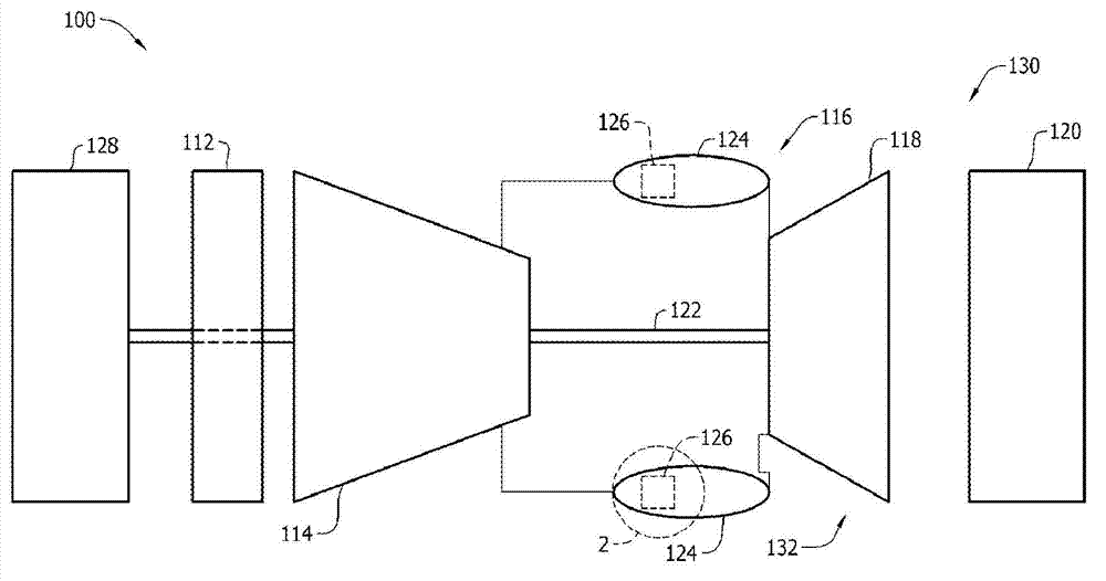
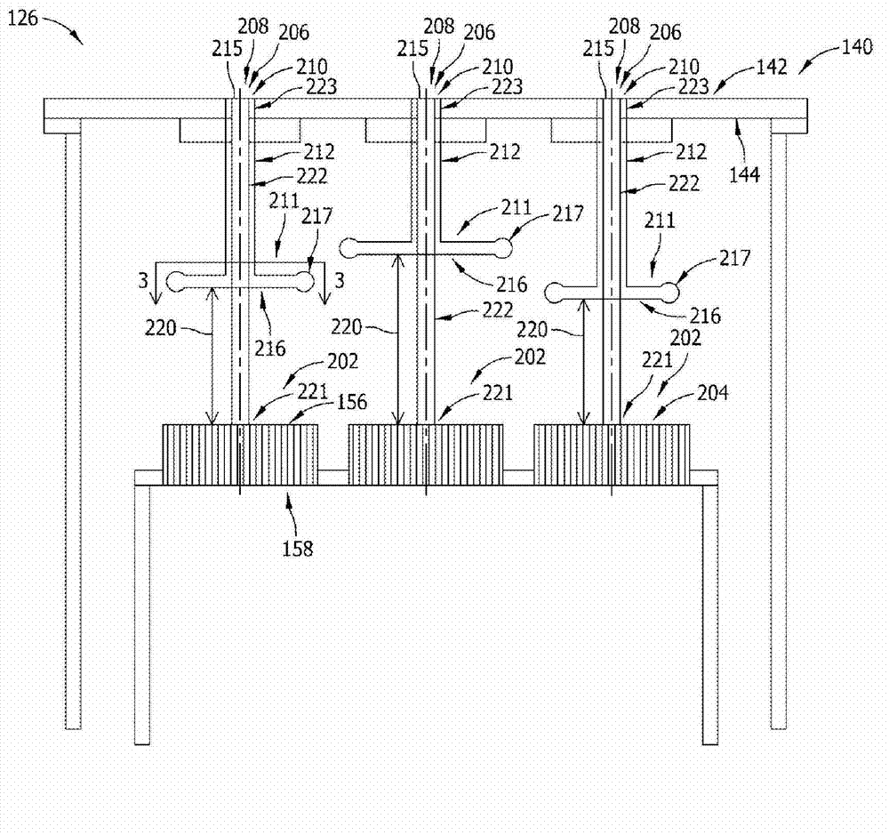
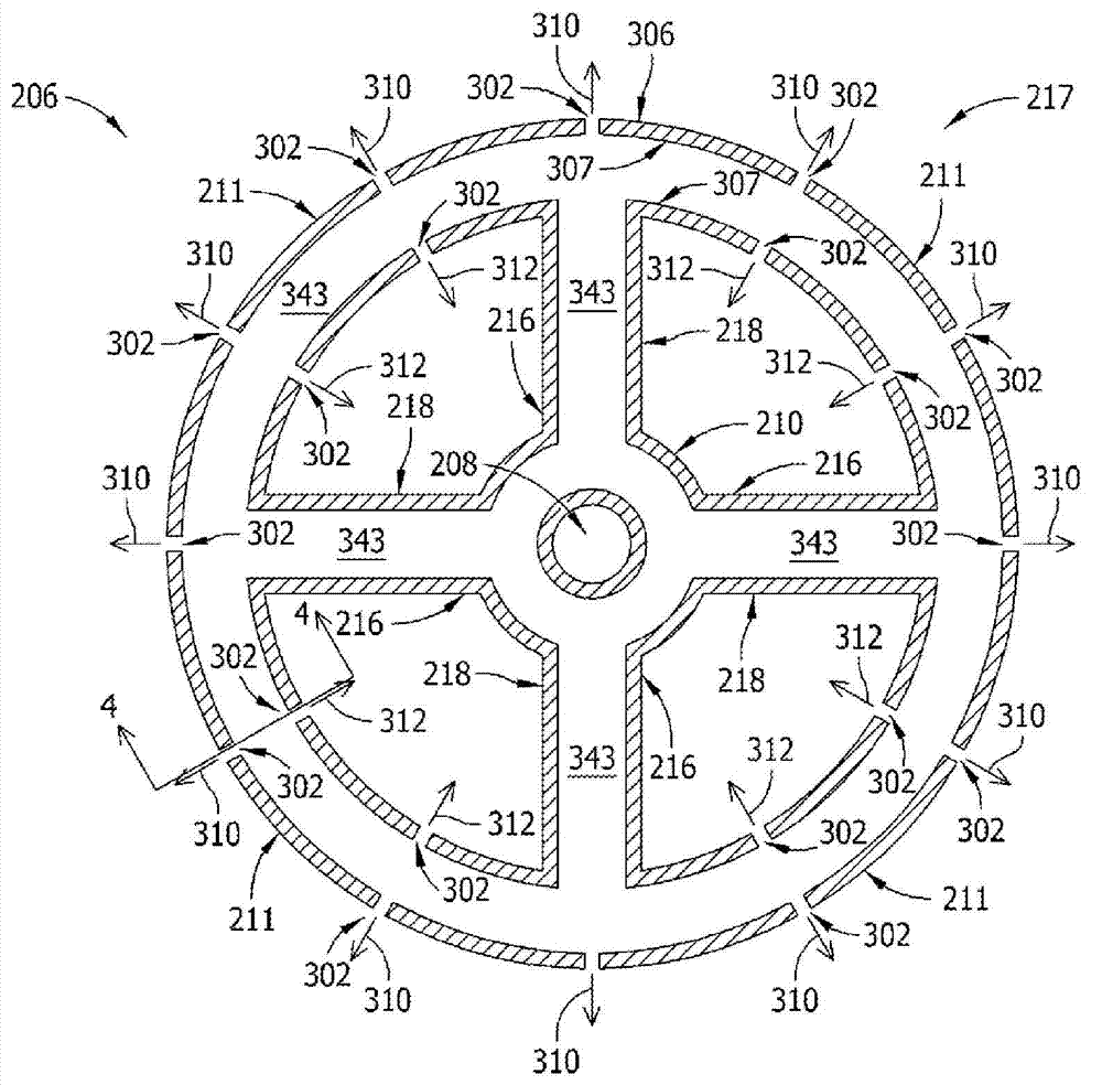
[0015] The exemplary apparatus, systems, and methods described herein overcome at least some of the known disadvantages associated with at least some known turbine engine combustion systems that introduce vibrational energy therein and / or down operation. Embodiments described herein provide a fuel injection assembly that may be used with a turbine engine to facilitate substantially reducing dynamic pressure oscillations and / or localized peak temperatures within a combustor. The fuel injection assembly includes a plurality of tube assemblies, where each tube assembly of the plurality of tube assemblies includes a plurality of tubes. At least one injection system is coupled to at least one tube assembly of the plurality of tube assemblies. The injection system includes a fuel delivery conduit and a fluid supply member coupled to the fuel delivery conduit, wherein the fluid supply member is positioned at a distance upstream relative to the tube assembly. The fluid supply member...


PUM


Abstract

A fuel injection assembly for use in a turbine engine is provided. The fuel injection assembly includes a plurality of tube assemblies wherein each of the plurality of tube assemblies includes a plurality of tubes. At least one injection system is coupled to at least one tube assembly of the plurality of tube assemblies. The injection system includes a fuel delivery pipe and a fluid supply member coupled to the fuel delivery pipe, wherein the fluid supply member is positioned a predefined distance upstream from the tube assembly and includes at least one first portion having an annular end portion. The annular end portion includes at least one opening for delivering fluid toward the tube assembly for reducing dynamic pressure oscillations and / or reducing the temperature within a combustor during operation of the turbine engine.

Description

technical field [0001] The subject matter disclosed in this specification relates generally to turbine engines, and more particularly, to fuel injection assemblies for use in turbine engines. Background technique [0002] At least some known turbogenerators are used in cogeneration facilities and power plants. Such engines may have high demands on specific work and power per unit mass flow. Such a turbine engine may include at least one combustor including a plurality of fuel nozzles that may be coupled within the combustor. Compressed air flows through and through the nozzles to reach the combustion zone within the combustor. As the air travels through and past the fuel nozzles, fuel is injected into the air stream, and the air and fuel mix together to create a fuel-air mixture that is ignited in the combustion zone of the combustor. To increase operating efficiency, at least some known turbine engines, such as gas turbine engines, operate at elevated combustion temperat...

Claims


Application Information

Patent Timeline
Patent Type & Authority Applications(China)
IPC IPC(8): F23R3/28
CPCF23R3/286F23R2900/00002Y10T29/49229
Inventor 严钟昊T.E.约翰逊吴春阳
Owner GENERAL ELECTRIC CO
Features
  • R&D
  • Intellectual Property
  • Life Sciences
  • Materials
  • Tech Scout
  • Unparalleled Data Quality
  • Higher Quality Content
  • 60% Fewer Hallucinations
Learn More