Cable insulation test system

A test system and cable insulation technology, which is applied in the field of electric power, can solve problems such as poor contact, easy residual charge in cables, and slow discharge speed, and achieve the effects of reducing the possibility of wiring errors, safe and reliable discharge devices, and rapid discharge processes

Active Publication Date: 2013-08-14
STATE GRID CORP OF CHINA +1
View PDF7 Cites 15 Cited by
  • Summary
  • Abstract
  • Description
  • Claims
  • Application Information

AI Technical Summary

Problems solved by technology

[0004] 1. In the process of sequentially measuring the phase-to-ground, phase-to-phase insulation resistance and discharge, it is necessary to repeatedly disassemble and assemble the connecting wires, which is time-consuming, laborious, and error-prone;
[0005] 2. The line connection is usually connected by crocodile clips, which has disadvantages such as poor contact and short service life;
[0006] 3. The operating space is small, and the cables are generally located at the bottom of the switch cabinet. When the crocodile clip is used to connect, the line of sight is blocked, the operation is difficult, and it may not be possible to keep a sufficient safety distance, causing serious accidents such as personal electric shock;
[0007] 4. When the cable is discharged, if the method of directly connecting the cable conductor to the grounding pole is used, it is easy to cause ignition and discharge, which seriously threatens the personal safety of the test personnel and the safe operation of the equipment; The method of short-circuiting the grounding pole with wooden strips and other materials, the discharge speed is slow, and it is unknown whether the discharge is clean, and the cable is prone to residual charge, causing danger; Disadvantages such as not easy to carry;
[0008] 5. During the cable discharge process, the insulation resistance meter cannot be manually operated, so at least two workers are required to complete it, which wastes manpower and time, and is prone to errors.
[0009] Through searching, no published patent documents identical with the application of the present invention have been found

Method used


Image

  • Cable insulation test system
  • Cable insulation test system
  • Cable insulation test system

Examples


Embodiment Construction

[0026] In order to further understand the content, characteristics and effects of the present invention, the following examples are given, and detailed descriptions are given below with reference to the accompanying drawings. It should be noted that this embodiment is descriptive, not restrictive, and cannot thereby limit the protection scope of the present invention.

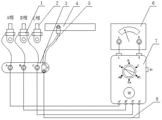
[0027] A cable insulation testing system, which consists of five parts: an insulation resistance meter 6, a cable junction plate 3, a test operation box 7, a grounding lead 5, and a cable clamp 1, wherein the test operation box is electrically connected to the insulation resistance meter, and the test operation box passes through the lead wire 8 Connect the cable junction board, the three-phase lines of the cable junction board are respectively connected to the three-phase lines (A phase, B phase and C phase) of the cable 2 through the cable clamp, and the cable junction board is connected to the ground electrod...


PUM


Abstract

The invention relates to a cable insulation test system which comprises five parts, including an insulated resistance meter, a cable wiring disc, a test operation box, a grounding lead and cable clamps, wherein the cable wiring disc is made of an insulated material, the whole cable wiring disc has a rectangular middle part and two semicircular side parts, three metal wiring columns are vertically fixed in the middle of the cable wiring disc, and one metal wiring column is vertically fixed on the lower right side of the metal wiring column; the test operation box is a sealed box body, the casing of the sealed box body is made of hard plastic and other insulated materials, the upper part of the test operation box is provided with two metal wiring columns, the lower part of the test operation box is provided with four metal wiring columns, a switch is arranged on the right side of the test operation box, and a six-segment mechanical change-over switch and a self-locking button are arranged on the panel of the test operation box; and the grounding lead is a multi-strand soft copper wire with insulated outer leather. During the measurement, the system does not need to change wiring, shortens the test time by about 80 percent, meanwhile remarkably lowers the probability of a wiring error, remarkably improves working efficiency, and ensures the safety of test process.

Description

technical field [0001] The invention belongs to the field of electric power, and relates to cable testing equipment, in particular to a cable insulation testing system. Background technique [0002] Cables are widely used in urban distribution networks, and faults will inevitably occur during use. When a ground fault or a phase-to-phase fault occurs in the cable, it is necessary to use an insulation resistance meter and other instruments to measure the insulation resistance of each phase and phase to determine which phase has a short circuit to ground, or which two phases have a short circuit between phases. Since there is a distributed capacitance between the cable and the earth, the process of measuring the cable insulation resistance with an insulation resistance meter will charge the cable; if the cable is not grounded and discharged in time, the residual charge in the cable will cause a voltage difference between the cable and the earth , threatening the safety of pers...

Claims


Application Information

Patent Timeline
Patent Type & Authority Applications(China)
IPC IPC(8): G01R27/18
Inventor 张愉郑启林都志军刘荣浩李宝利李洋郭跃伟霍爽毕鹏冯潇楠
Owner STATE GRID CORP OF CHINA
Why Eureka
Try Eureka