Silicon wafer prealignment measuring apparatus

A measurement device and pre-alignment technology, which is applied in the direction of exposure devices, optics, and instruments in photolithography, can solve problems affecting thermal stability, loose structure layout, and unfavorable component modularization, so as to improve pre-alignment accuracy, Strong structural independence and reduced temperature influence

Active Publication Date: 2013-08-14
SHANGHAI MICRO ELECTRONICS EQUIP (GRP) CO LTD +1
View PDF7 Cites 1 Cited by
  • Summary
  • Abstract
  • Description
  • Claims
  • Application Information

AI Technical Summary

Problems solved by technology

[0004] 1. The image processing modules 261, 262, and 263 of the three vision systems are close to the projection objective lens and the main substrate, and their heat sources affect their thermal stability; 2. The vertical layout of the vision system affects the radial dimension design of the lens, and requires the main substrate to be Opening holes affect the structural stability of the main substrate; 3. Due to the vertical layout of the vision system, the three sets of vision cannot be arranged orthogonally. The orthogonal arrangement is most beneficial for improving the accuracy of the secondary pre-alignment measurement; 4. The wiring of the vision system Wiring inevitably enters the design of the whole machine, which increases the complexity of the design, which is not conducive to the modularization and independence of this component, and the integration and debugging are inconvenient
Due to the loose structure arrangement, the component is difficult to assemble and test offline, and the manufacturing risk is high

Method used


Image

  • Silicon wafer prealignment measuring apparatus
  • Silicon wafer prealignment measuring apparatus
  • Silicon wafer prealignment measuring apparatus

Examples


Embodiment Construction

[0030] Specific embodiments of the present invention will be described in detail below in conjunction with the accompanying drawings.

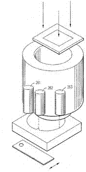
[0031] After Wafer handling transfers silicon wafers through pre-alignment, the eccentricity and deflection are initially compensated. Afterwards, the transfer manipulator continues to transport the silicon wafers to the inside of the lithography machine. The relative drift of the frame will cause a large positional disturbance to the silicon wafers transferred to the handover position of the workbench by Wafer handling. In order to make up for these losses and further improve the accuracy of the wafer, the silicon wafers need to be pre-aligned twice at the handover position. Through the secondary pre-alignment, that is, through the measurement of the pre-alignment measurement device in the present invention, the residual eccentricity and deflection of the silicon wafer are obtained, and the residual error is compensated by the workbench. The ...


PUM


Abstract

A silicon wafer prealignment measuring apparatus comprises three visual photoetching machines and a shell and is used for prealigning a detected silicon wafer disposed on a workbench, the shell is used for fixing the three visual photoetching machines, each of the three visual photoetching machines comprises imaging CCD, an imaging optical path, an illuminating optical path and a reflector, and light from the tested silicon wafer undergoes angle change through the reflector and enters the imaging CCD through the imaging optical path; the imaging optical paths of the three visual photoetching machines are in a same plane paralleling to the plane in which the detected silicon wafer is positioned; and the three visual photoetching machines respectively acquire three-segment edge information of the detected silicon wafer, and calculate according to the acquired silicon wafer edge information to obtain the residual eccentric error and the residual deflection error. The silicon wafer prealignment measuring apparatus has the advantages of prealignment precision increase, strong structural independence, compact structure, no restriction on the space of a projection object lens, strong offline adjusting flexibility, and reduced influences on the temperature of the surrounding microenvironment.

Description

technical field [0001] The invention relates to a pre-alignment measurement device, in particular to a silicon chip edge information measurement device. Background technique [0002] A lithographic apparatus is a device that exposes a mask pattern onto a silicon wafer. Lithography equipment is highly automated. It has a fully automatic silicon wafer servo system called wafer handling. Lithography equipment not only has the necessary productivity requirements for wafer handling to meet the production efficiency of the entire equipment, but also has a There are strict requirements on the accuracy of the transfer to the workbench. Since the silicon wafer has two geometric features of circle and notch, from the geometrical calculation, as long as enough feature points on the circumference of the silicon wafer are obtained, the center position and the direction of the notch of a silicon wafer can be obtained, and then the silicon wafer can be calculated in a relatively High cen...

Claims


Application Information

Patent Timeline
Patent Type & Authority Applications(China)
IPC IPC(8): G03F9/00G03F7/20
Inventor 王邵玉
Owner SHANGHAI MICRO ELECTRONICS EQUIP (GRP) CO LTD
Why Eureka
Try Eureka