3D laser printing method and system

A 3D laser and printing system technology, applied in the direction of optics, optical components, diffraction gratings, etc., can solve the problems of complex mechanical movement mechanism, unfavorable optical path stability, etc., and achieve simple system structure, good printing and imaging effect, and strong stereoscopic effect of 3D images Effect

Active Publication Date: 2013-08-14
SVG TECH GRP CO LTD
View PDF10 Cites 55 Cited by
  • Summary
  • Abstract
  • Description
  • Claims
  • Application Information

AI Technical Summary

Problems solved by technology

[0008] In order to realize continuous rather than discrete grating space-frequency conversion, one consideration is to set up multiple groups of prism beam splitting systems and lens concentrating systems with variable relative positions, and rotate the prism groups along the optical axis while rotating around the optical axis. Move up and down to realize continuous frequency conversion dot matrix holographic printing output, but the mechanical movement mechanism of this setting is complicated, which is not conducive to the stability of the optical path

Method used


Image

  • 3D laser printing method and system
  • 3D laser printing method and system
  • 3D laser printing method and system

Examples


Embodiment 1

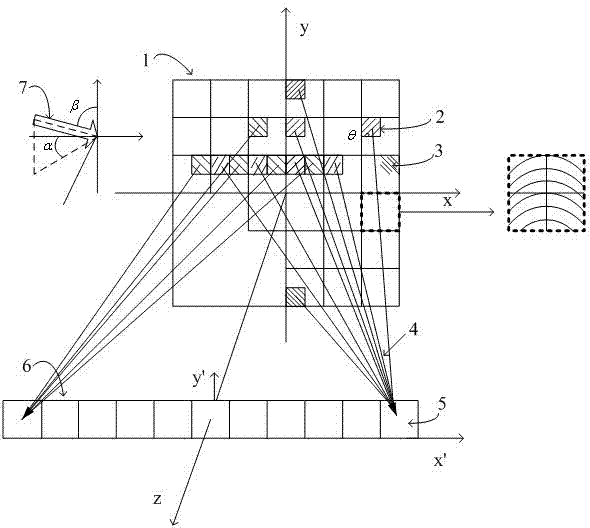
[0040] See attached figure 1 , is a schematic diagram of a four-parameter (x, y, Λ, θ) three-dimensional image with continuously variable grating space frequency and orientation and its display effect in this embodiment.

[0041] The three-dimensional image 1 of this embodiment is located at the coordinate plane (x, y), and is composed of a series of diffractive pixels 2 filled by a group of pixel gratings 3 with specific space frequency and orientation. The space frequency of the pixel grating in the image 1 changes gradually from top to bottom, depending on the direction of the illumination light and the position of the observation window. Generally, the space frequency gradually increases from the top to the bottom of the image. The three-dimensional image is diffracted under the illumination of the illumination light 7, and a slit-shaped observation window 6 is formed on the (x', y') plane at a distance from the image plane Z, and the observation window 6 is composed of a ...

Embodiment 2

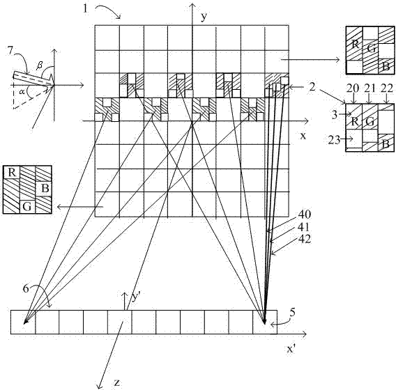
[0049] See attached figure 2 , is a schematic diagram of a four-parameter (x, y, Λ, θ) three-dimensional color image with continuously variable grating space frequency and orientation in this embodiment.

[0050] The three-dimensional color image 1 of this embodiment is located at the coordinate plane (x, y), and is composed of a series of diffraction pixels 2, and the diffraction pixels 2 are composed of red sub-pixels 20, green sub-pixels 21, and blue sub-pixels 22, so The sub-pixels of the above three colors are filled by a group of gratings 3 and blank areas 23 with specific space frequencies and orientations. The space frequency of the pixel grating in image 1 changes gradually from top to bottom, depending on the direction of the illumination light and the position of the observation window. Generally, the space frequency gradually increases from the top to the bottom of the image. The three-dimensional color image is diffracted under the illumination of the illuminati...

Embodiment 3

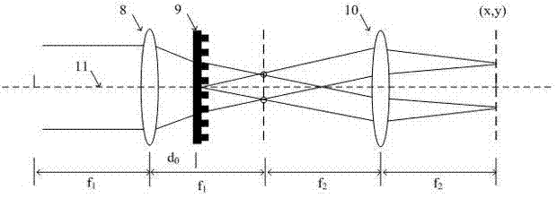
[0054] see image 3 Shown is a schematic diagram of a four-parameter (x, y, Λ, θ) optical modulation method with continuously variable grating space frequency and orientation.

[0055] In this embodiment, a four-parameter (x, y, Λ, θ) optical modulation method with continuously variable grating space frequency and orientation. including focal length f 1 The first Fourier transform lens 8 with focal length f 2 The 4F optical system and the diffraction grating 9 are constituted by the second Fourier transform lens 10 lenses. The diffraction grating 9 is located between the first Fourier transform lens and the focal length of the first Fourier transform lens. The diffraction grating can move along the optical axis 11 or rotate around the optical axis 11 .

[0056] The method changes the distance d between the diffraction grating and the first Fourier transform lens by moving the diffraction grating 9 0 , realizing the continuous modulation of the grating space frequency Λ pa...


PUM


Abstract

The invention discloses a 3D laser printing method and system. A four-parameter continuous modulation laser printout method is adopted to prepare a 3D image consisting of diffraction pixels arranged according to the position coordinates and provided with both a specific grating space frequency and an angle of orientation; the modulation method of parameters of grating stripes in the diffraction pixels is realized on the basis of a 4F imaging system and a diffraction grating; the 4F imaging system comprises a first Fourier transformation lens or lens group and a second Fourier transformation lens or lens group; the diffraction grating is placed between the first Fourier transformation lens or lens group and the second Fourier transformation lens or lens group; the distance between the diffraction grating and the first Fourier transformation lens or lens group is changed to realize continuous modulation of the space frequency of the grating stripes; and the diffraction grating is rotated to realize continuous modulation of the grating orientation angle of the grating stripes. The 3D laser printing method and system realize continuous adjustment of the space frequency and the orientation of the grating, and encodes on the basis of the four-parameter micro-nano structure with continuously changeable space frequency and orientation of the grating to form a 3D color image.

Description

technical field [0001] The invention relates to a three-dimensional image printing method and system, in particular to a laser printing method and system for expressing three-dimensional images using micro-nano structures. Background technique [0002] From a physical meaning, expressing a two-dimensional (2D) image requires at least three parameters: two plane position coordinate variables and one grayscale variable. Accordingly, if a certain method and device are used to output different gray values ​​at different coordinates, the printout of the planar image can be realized. Methods and systems such as laser printing and inkjet printing based on this principle have become indispensable tools for daily office work. [0003] To express a three-dimensional (3D) object, at least four independent variables are required: three-dimensional coordinate variables (x-y-z) and color (grayscale). If you want to express a color image that can display three-dimensional information on ...

Claims


Application Information

Patent Timeline
Patent Type & Authority Applications(China)
IPC IPC(8): G03H1/26G02B5/18G02B27/22G02B27/44
Inventor 陈林森楼益民浦东林袁晓峰朱鹏飞魏国军张瑾朱鸣李恒胡进申溯
Owner SVG TECH GRP CO LTD
Why Eureka
Try Eureka