High-precision spinning antenna reflecting surface and manufacturing method thereof

A reflective surface, high-precision technology, applied to antennas, antennas suitable for movable objects, electrical components, etc., can solve the problems of antenna reflective surface back frame structure design, complex processing technology, and difficult to meet the surface accuracy of communication technology. High requirements, affecting the surface accuracy of the reflective surface, etc., to achieve the effect of beautiful appearance, improved rigidity, and good energy absorption effect

Active Publication Date: 2013-08-14
NO 54 INST OF CHINA ELECTRONICS SCI & TECH GRP
View PDF10 Cites 11 Cited by
  • Summary
  • Abstract
  • Description
  • Claims
  • Application Information

AI Technical Summary

Problems solved by technology

The disadvantages of the traditional spin-formed antenna reflector above are:
[0004] 1. The surface accuracy is low, and it is difficult to meet the high requirements of communication technology for surface accuracy;
[0005] 2. The structure design and processing technology of the back frame of the antenna reflector are complex, heavy and expensive;
[0006] 3. The back frame of the antenna reflective surface has its own stress after forming. During the connection process between the back frame and the reflective surface and after the connection is completed, it is easy to cause deformation of the reflective surface, poor shape retention, and affect the surface accuracy of the reflective surface;
[0007] 4. There is a stress concentration phenomenon at the connection point between the back frame and the reflective surface, and the antenna has poor shock resistance. The external environmental load is easily caused to deform and damage the reflective surface during travel.
[0008] Chinese Patent No. 200910082085.1, titled "A Reflecting Surface Antenna with Double Shell Structure" discloses a method for manufacturing a reflective surface antenna with a double shell structure. The edge part of the aperture antenna block panel structure is easy to cause warpage, which reduces the deviation of the deformation surface, but the design structure still continues the design idea of ​​rib support, especially for the manufacture of small and medium-sized high-precision antenna reflection surfaces , there are also the above disadvantages

Method used


Image

  • High-precision spinning antenna reflecting surface and manufacturing method thereof
  • High-precision spinning antenna reflecting surface and manufacturing method thereof
  • High-precision spinning antenna reflecting surface and manufacturing method thereof

Examples


Embodiment Construction

[0038] combine Figure 1 to Figure 8 , the present invention will be further described below.

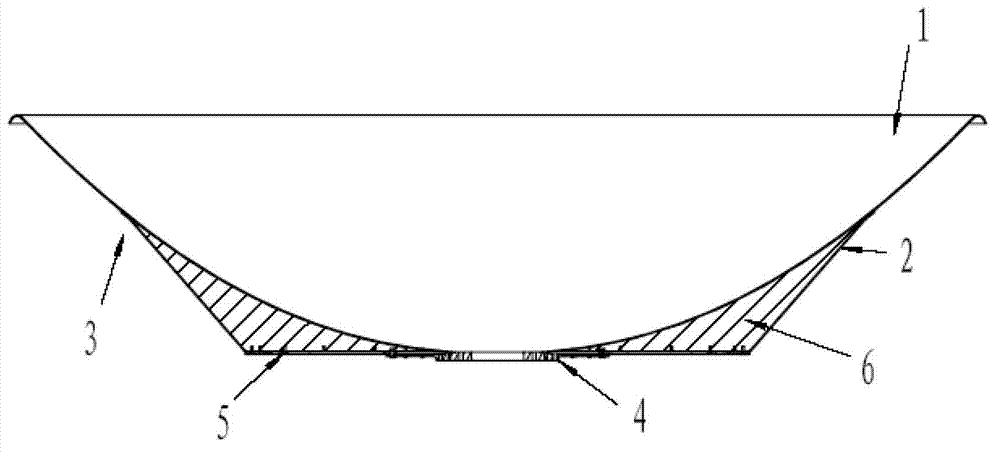
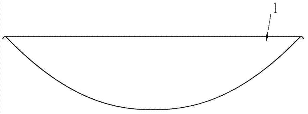
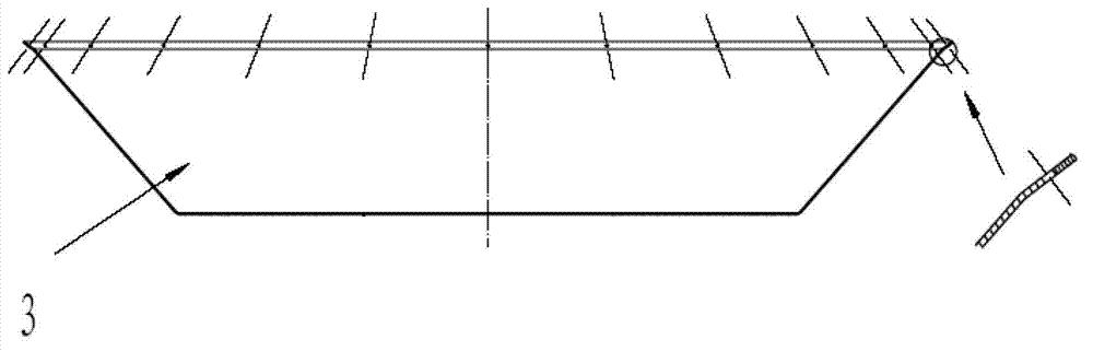
[0039] A high-precision spinning antenna reflective surface, comprising a spinning-formed main reflective surface 1 and a support body located on the back of the main reflective surface 1, the support body is a tray structure designed coaxially with the main reflective surface, the tray plate Bonding is carried out along the inner side wall of 3 and the outer surface of the main reflective surface. A feed hole is opened at the center of the main reflective surface, and a through hole is opened at a position corresponding to the feed source hole on the tray bottom plate 5 . A boss 4 is arranged at the position corresponding to the through hole on the tray bottom plate 5, and the central hole of the boss coincides with the through hole. The inner contact surface of the boss 4 is bonded to the outer bottom surface of the main reflection surface. A plurality of foam pouring holes are ...


PUM


Abstract

The invention discloses a high-precision spinning antenna reflecting surface and a manufacturing method thereof, and relates to radar antenna manufacturing engineering field, in particular to manufacturing technique of main antenna reflecting surface spin forming and support body adhesive foam stabilization precision. The high-precision spinning antenna reflecting surface comprises a spinning formed main reflecting surface, a support body which is designed to be coaxial with the main reflecting surface, a foam materiel used for improving the strength and rigidity of the antenna reflecting surface, and a plurality of parts used for assembling. According to the invention, an adhesion process is adopted to change a traditional spinning antenna reflecting surface from a point-supported mode to a curve-supported mode, and a foam sandwich structure is skillfully adopted, so that the high-precision (the surface precision is 0.3 mm RMS ) spinning antenna reflecting surface can be manufactured without using a high-precision parabolic mold; and the high-precision spinning antenna reflecting surface has the advantages of strong rigidity, high strength, small deformation, good shock resistance and simple processing technique, and is particularly suitable for radar antenna devices on mobile carriers, such as vehicles and ships.

Description

technical field [0001] The invention relates to a high-precision spinning antenna reflective surface and a manufacturing method in the field of radar antenna manufacturing engineering. It is especially suitable for the batch manufacturing technology of small and medium-sized high-precision antenna reflectors on mobile carriers such as vehicles and ships. Background technique [0002] With the development of communication technology, the working frequency band is getting higher and higher, and it is constrained by the harsh working environment of vehicle-mounted, ship-borne, and ship-borne radar antennas, which puts forward higher requirements for the accuracy, stiffness, strength, and durability of radar antenna reflective surfaces. . [0003] Spinning forming technology is especially suitable for the manufacture of small and medium-sized antenna reflectors. The traditional spinning forming antenna surface is mainly completed through the following processes: blanking - pref...

Claims


Application Information

Patent Timeline
Patent Type & Authority Applications(China)
IPC IPC(8): H01Q15/16H01Q1/27
Inventor 王海东刘利文石晓改张伟明金超杨晓琦王大为
Owner NO 54 INST OF CHINA ELECTRONICS SCI & TECH GRP
Why Eureka
Try Eureka