
Power gating circuit

A power gating and circuit technology, applied in the direction of electrical components, electronic switches, pulse technology, etc., can solve problems such as ground bounce and output voltage fluctuations

Active Publication Date: 2013-08-14
ZHUHAI JIELI TECH
View PDF4 Cites 4 Cited by
  • Summary
  • Abstract
  • Description
  • Claims
  • Application Information

AI Technical Summary

Problems solved by technology

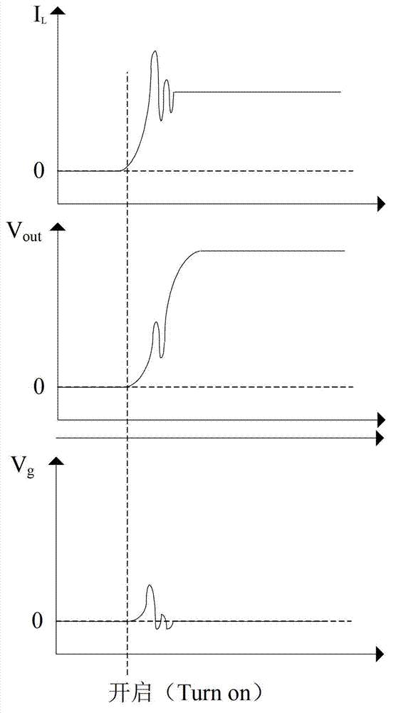
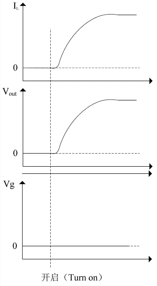
[0005] Based on this, it is necessary to provide a more stable and reliable power gating circuit for circuit working state switching to address the above-mentioned problems of ground bounce and output voltage fluctuations at the moment of turning on.

Method used


Image

  • Power gating circuit
  • Power gating circuit
  • Power gating circuit

Examples


Embodiment Construction

[0022] The specific implementation manner of the power gating circuit of the present invention will be described in detail below in conjunction with the accompanying drawings.

[0023] refer to Figure 4 as shown, Figure 4 is a schematic structural diagram of a power gating circuit in one embodiment. The power gating circuit consists of connecting the power supply V DD and the output power tube 01 between the circuit module 02, and the pull-up circuit 03, the weak current source 04, the pull-down circuit 05 and the voltage detection circuit 06.

[0024] The pull-up circuit 03 is connected to the power supply V DD Between the grid of the output power tube 01, the weak current source 04, the pull-down circuit 05, and the voltage detection circuit 06 are connected to the grid of the output power tube 01, and the voltage detection circuit 06 is connected to the pull-down circuit 05.

[0025] When the output power transistor 01 needs to be turned off, the pull-up circuit 03 p...


PUM


Abstract

A power gating circuit comprises an output power tube connected between a power supply and a circuit module, a pull-up circuit, a weak current source, a pull-down circuit and a voltage detection circuit, wherein when the output power tube is closed, the pull-up circuit pulls up a grid electrode of the output power tube to the power supply; when the output power tube is opened, the weak current source outputs a weak pull-down current to the grid electrode of the output power tube, and the voltage detection circuit detects the voltage value of the grid electrode of the output power tube; and when the voltage value is smaller than the set threshold value, the pull-down circuit is controlled to forcefully pull down the grid electrode of the output power tube to the ground. The power gating circuit can solve problems of ground bounce and output voltage fluctuation at the moment of opening the circuit, can enable switching of working states of the circuit to be more stable and reliable, can effectively control the opening speed and the opening time of the output power tube, and is applicable to circuits with different requirements.

Description

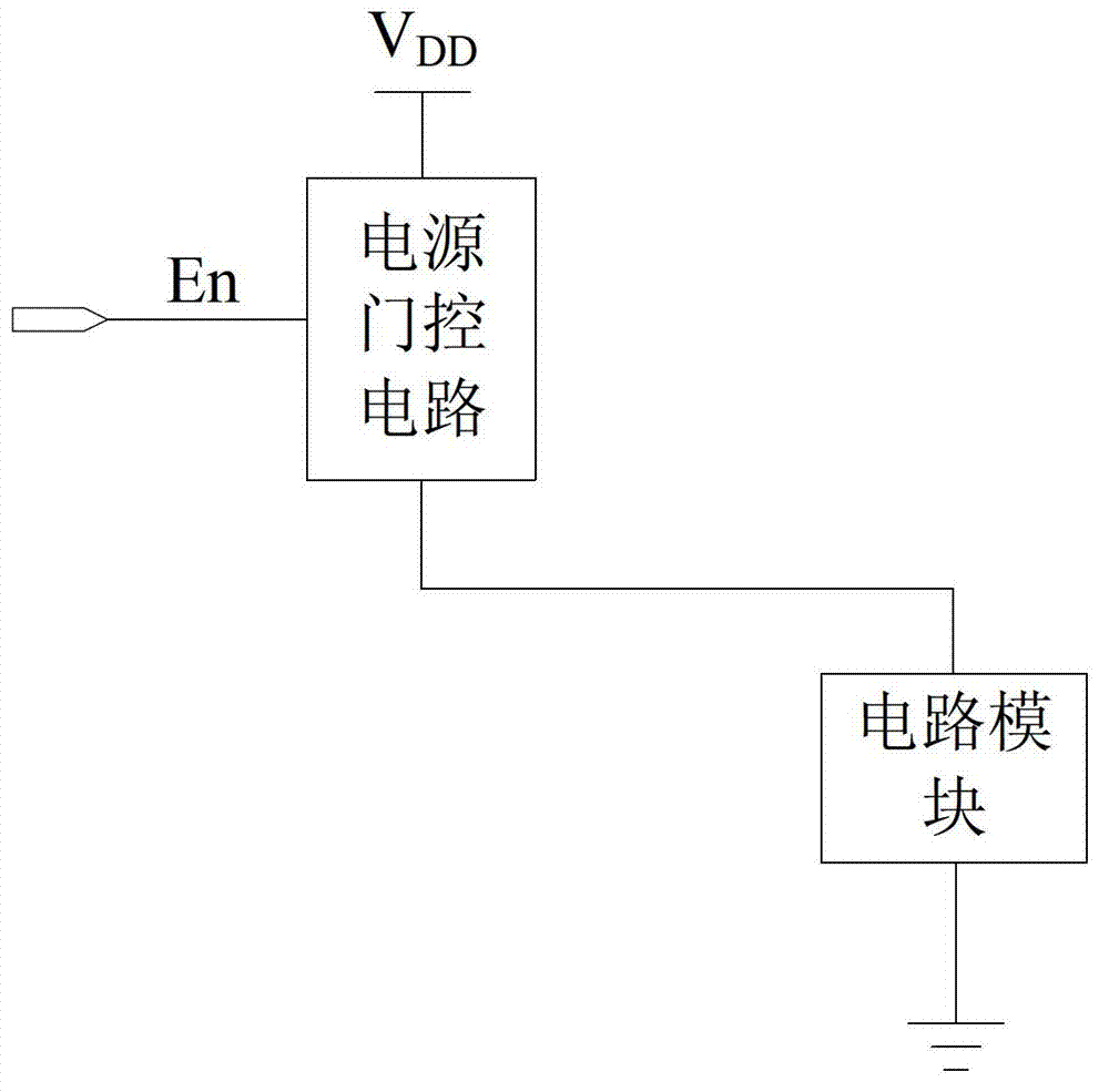
technical field [0001] The invention relates to power gating technology, in particular to a power gating circuit. Background technique [0002] The power gating circuit is a common technology to reduce the leakage power consumption of the circuit module in sleep or standby mode by controlling the power supply of the circuit module. It is widely used in the design of integrated circuits. The controlled Circuit modules can be inside or outside the chip. Such as figure 1 as shown, figure 1 It is a schematic structural diagram of a power gating circuit. The controlled circuit module 02 requires higher requirements for the power gating circuit due to the influence of parasitic inductance and parasitic resistance of the wiring. [0003] Such as figure 2 as shown, figure 2 It is a schematic structural diagram of a traditional power gating circuit, which uses an enable signal En to control the switch of the output power transistor 01 to control the power supply of the circuit...

Claims


Application Information

Patent Timeline
IPC IPC(8): H03K17/16H03K17/687
Inventor 钟汶林
Owner ZHUHAI JIELI TECH
Learn More