
Insulation resistance measurement circuit having self-est function without generating leakage current

一种绝缘电阻测量、绝缘电阻的技术,应用在具有自检功能的不产生泄漏电流的绝缘电阻测量电路领域,能够解决电路设计限制等问题

Active Publication Date: 2013-08-14
SK ON CO LTD
View PDF8 Cites 24 Cited by
  • Summary
  • Abstract
  • Description
  • Claims
  • Application Information

AI Technical Summary

Problems solved by technology

However, the disadvantage of this method is that since the charging current of the coupling capacitor and the discharging current of the coupling capacitor must pass through the same circuit, there are many restrictions on the circuit design

Method used


Image

  • Insulation resistance measurement circuit having self-est function without generating leakage current
  • Insulation resistance measurement circuit having self-est function without generating leakage current
  • Insulation resistance measurement circuit having self-est function without generating leakage current

Examples


Embodiment Construction

[0042] Hereinafter, embodiments of the present invention will be described in detail with reference to the accompanying drawings.

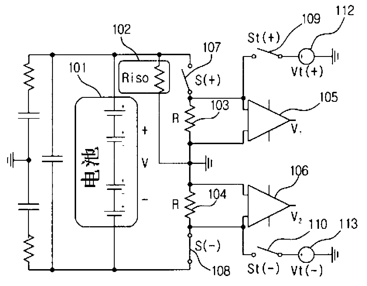
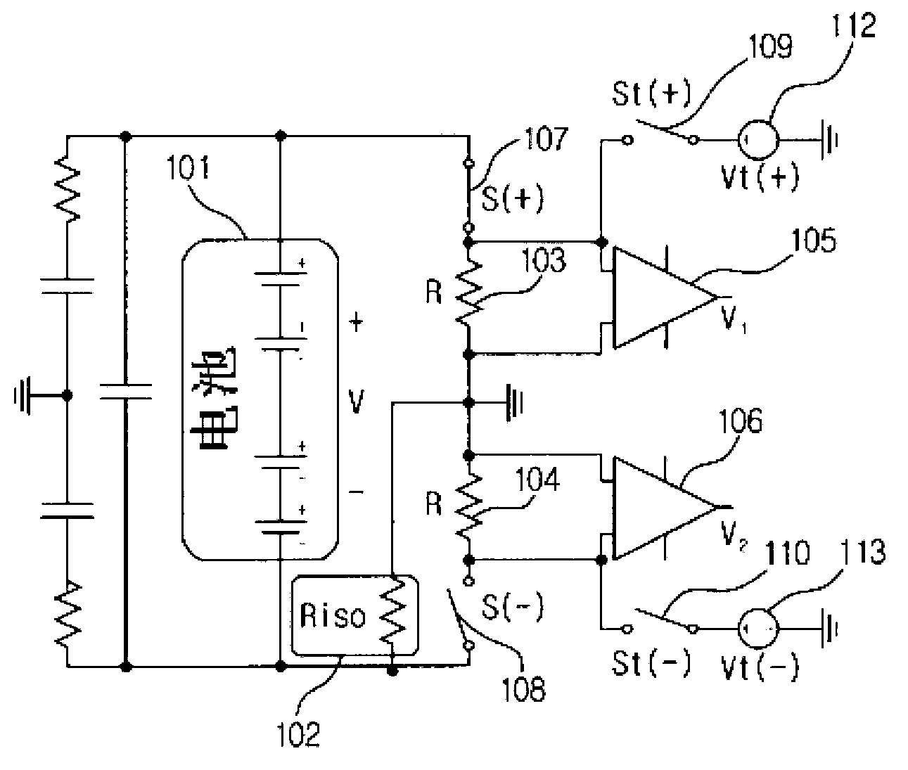
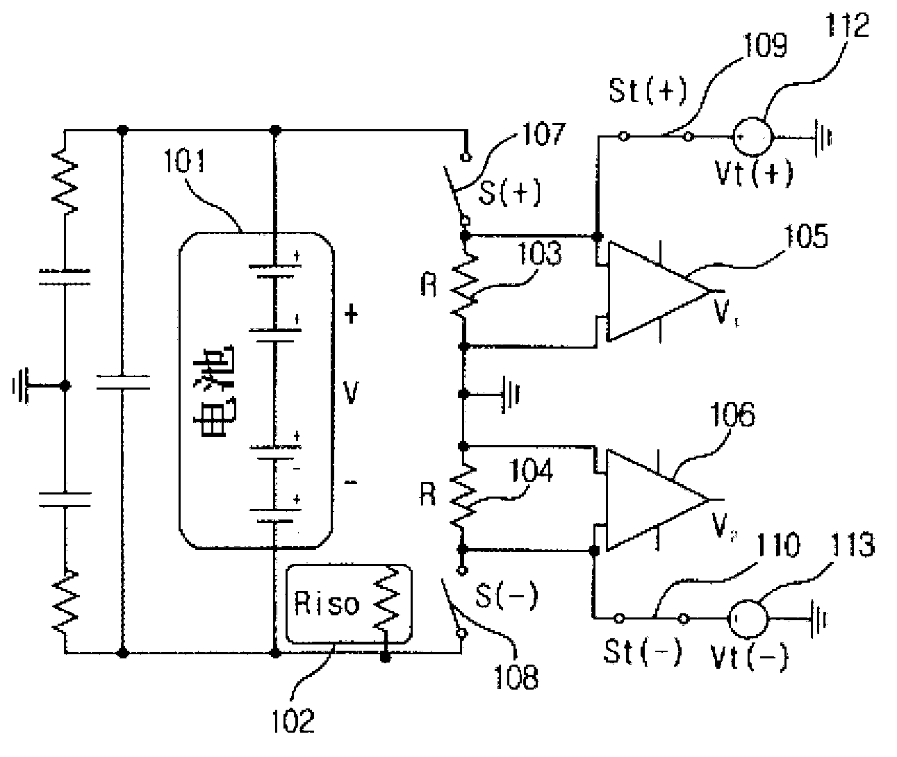
[0043] Figures 1 to 3 is a circuit diagram showing the setup of an insulation resistance measurement circuit according to an embodiment of the present invention.

[0044] figure 1 is a circuit diagram according to an embodiment of the present invention, which shows the connection of the insulation resistance measurement circuit when the positive electrode of the insulation resistance measurement battery fails. figure 2 is a circuit diagram according to an embodiment of the present invention, which shows the connection of the insulation resistance measurement circuit when the negative electrode of the insulation resistance measurement battery fails. image 3 It is a circuit diagram according to an embodiment of the present invention, which shows the connection of the insulation resistance measurement circuit in the case of self-test.

[0045] ...


PUM


Abstract

Provided is an insulation resistance measurement circuit including: a source resistance unit including a first source resistance unit connected to a positive terminal of an insulation resistance measurement battery and a second source resistance unit connected to a negative terminal of the insulation resistance measurement battery and the first source resistance unit; a voltage sensing unit including a first operational amplifier sensing the voltage of the first source resistance unit, as a first voltage, and the voltage of the second source resistance unit, as a second voltage; a leakage current interrupting unit including a first switch connected to the positive terminal of the insulation resistance measurement battery and the first source resistance unit and a second switch connected to the negative terminal of the insulation resistance measurement battery and the second source resistance unit; a measurement circuit testing unit including a third switch connected to the first operational amplifier and a first voltage source and a fourth switch connected to the second operational amplifier and a second voltage source; and an insulation resistance measurement unit measuring insulation resistance of the insulation resistance measurement battery through the first and second voltages.

Description

technical field [0001] The present invention relates to an insulation resistance measuring circuit, and more particularly, to an insulation resistance measuring circuit in which the opening and closing of the first and second switches are controlled so that no leakage current is generated during the measurement of the insulation resistance, And after the first and second switches are opened and the third and fourth switches are closed, voltages output by the first and second operational amplifiers are measured for self-test of the insulation resistance measuring circuit. Background technique [0002] Hybrid vehicles using high voltage batteries have systems for automatically cutting power to the main high voltage battery in emergency situations. The emergency situation refers to the excessive short circuit caused by the failure of the relevant components, the excessive short circuit caused by the short-term blockage of the component failure due to the dielectric breakdown, a...

Claims


Application Information

Patent Timeline
Patent Type & Authority Applications(China)
IPC IPC(8): G01R27/08G01R31/02
CPCB60L3/0069G01R31/025G01R27/14G01R27/025G01R35/00G01R31/52
Inventor 梁正焕
Owner SK ON CO LTD
Learn More