Method for estimating amount of liquid water inside fuel cell, method for estimating amount of liquid water discharged from fuel cell, device for estimating amount of liquid water inside fuel cell, and fuel cell system

A fuel cell, water quantity technology, applied in fuel cells, fuel cell additives, circuits, etc., can solve problems such as insufficient moisture state detection accuracy

Inactive Publication Date: 2013-08-14
TOYOTA JIDOSHA KK
View PDF6 Cites 17 Cited by
  • Summary
  • Abstract
  • Description
  • Claims
  • Application Information

AI Technical Summary

Problems solved by technology

However, in order to properly control the water state inside the fuel cell, the conventional detection accuracy of the water state inside the fuel cell is not sufficient.

Method used


Image

  • Method for estimating amount of liquid water inside fuel cell, method for estimating amount of liquid water discharged from fuel cell, device for estimating amount of liquid water inside fuel cell, and fuel cell system
  • Method for estimating amount of liquid water inside fuel cell, method for estimating amount of liquid water discharged from fuel cell, device for estimating amount of liquid water inside fuel cell, and fuel cell system
  • Method for estimating amount of liquid water inside fuel cell, method for estimating amount of liquid water discharged from fuel cell, device for estimating amount of liquid water inside fuel cell, and fuel cell system

Examples


no. 1 example

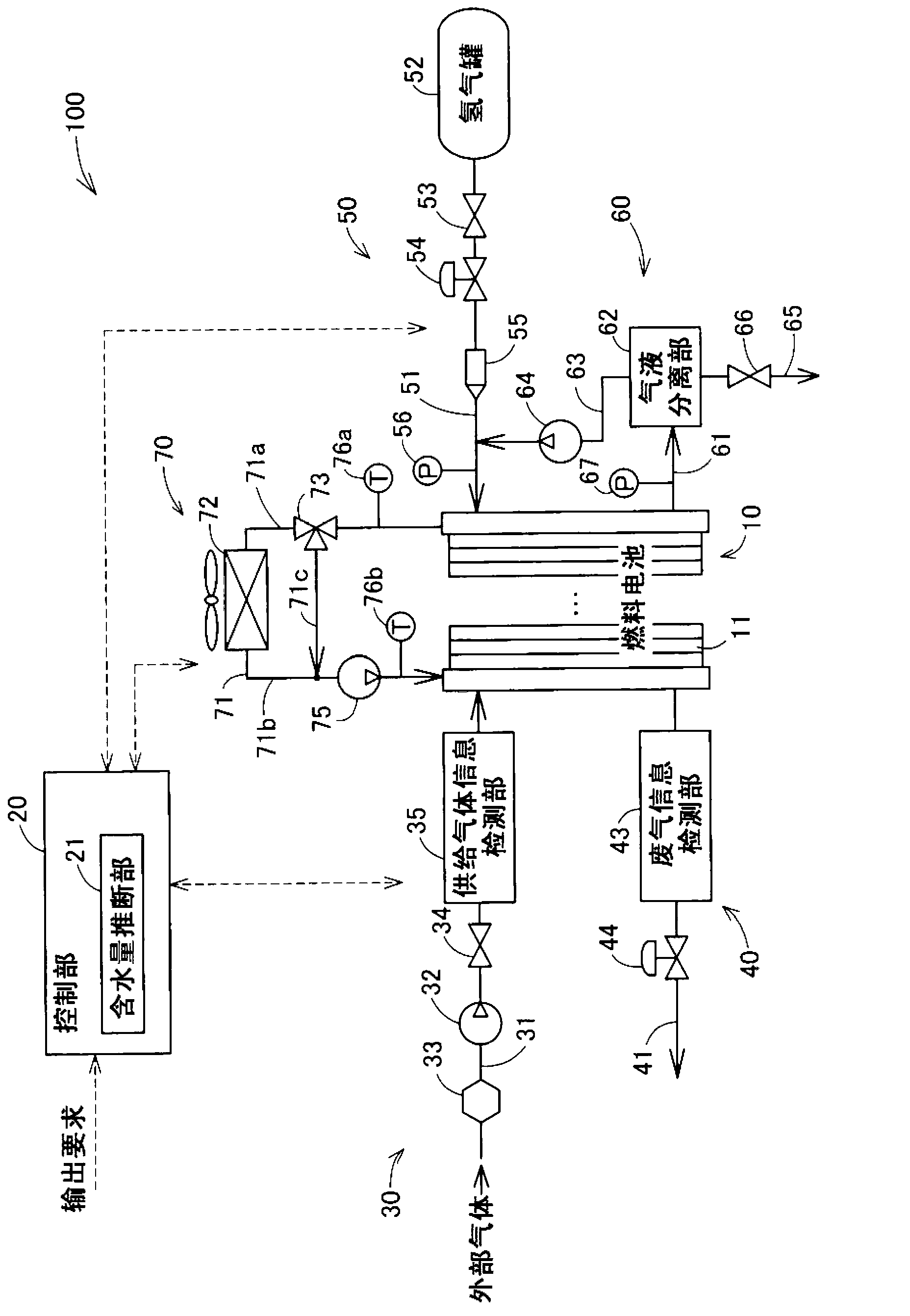
[0093] figure 1 It is a schematic diagram showing the configuration of a fuel cell system as an embodiment of the present invention. This fuel cell system 100 is mounted on a fuel cell vehicle, and outputs electric power used as driving force in response to a driver's request. The fuel cell system 100 includes a fuel cell 10 , a control unit 20 , a cathode gas supply unit 30 , a cathode gas discharge unit 40 , an anode gas supply unit 50 , an anode gas circulation discharge unit 60 , and a refrigerant supply unit 70 .

[0094] The fuel cell 10 is a solid polymer type fuel cell that receives supply of hydrogen gas (anode gas) and air (cathode gas) as reaction gases to generate electricity. The fuel cell 10 has a stack structure in which a plurality of power generators 11 also called cells are stacked. Each power generator 11 has: a membrane electrode assembly (not shown), which is a power generator in which electrodes are arranged on both surfaces of an electrolyte membrane; ...

no. 2 example

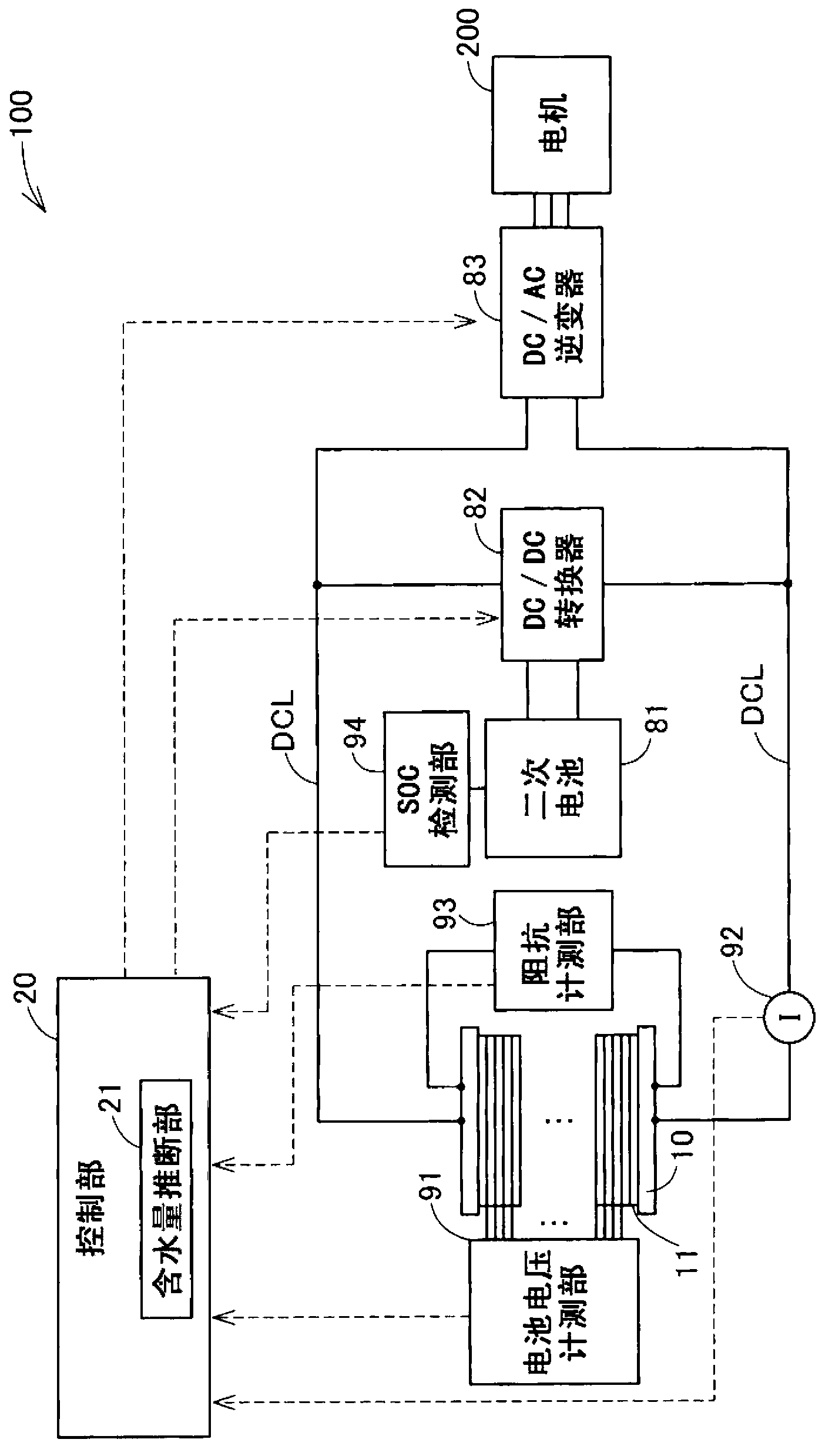
[0176] Figure 7 is a schematic diagram showing the configuration of a fuel cell system 100A as a second embodiment of the present invention. Figure 7 Except for the following figure 1 In substantially the same way, the content is that the anode gas supply part 50A is provided with the supply gas information detection part 57 instead of the inlet pressure measurement part 56, and the anode gas circulation discharge part 60A is provided with the exhaust gas information detection part 68. Instead of the outlet pressure measuring part 67. In addition, the electrical structure of the fuel cell system 100A of the second embodiment is the same as that of the fuel cell system 100 of the first embodiment ( figure 2 ).

[0177] As described above, in the fuel cell system 100 of the first embodiment, the water content of the fuel cell 10 is estimated ( image 3 ). In contrast, in the fuel cell system 100A of the second embodiment, the water content of the fuel cell 10 is estimate...

no. 3 example

[0227] Figure 13 is a flowchart showing the processing procedure of the water content estimation process executed by the water content estimation unit 21 in the fuel cell system according to the third embodiment of the present invention. Figure 13 In addition to adding steps S25 and S45, the same Figure 9 Much the same. In addition, the structure of the fuel cell system of the third embodiment is the same as that of the fuel cell system 100A of the second embodiment ( figure 2 , Figure 7 ).

[0228] Here, the inventors of the present invention have found out that when the supply flow rate of the reactant gas to the fuel cell 10 in operation, for example, is temporarily stopped and then resumed, it is suddenly decreased and increased repeatedly. The amount of liquid water to be drained from the fuel cell 10 will increase. Therefore, when the water content estimating unit 21 of the third embodiment detects that the supply of the reaction gas is temporarily stopped base...


PUM


Abstract

Estimation values of the amount of liquid water inside a fuel cell during operation are sequentially acquired in each predetermined period by means of the following steps (a) to (d), and detection accuracy with respect to the moisture state inside the fuel cell is improved. (a) The previous estimation value is acquired. (b) A water discharge speed which is the amount of liquid water discharged from a fuel cell per unit time is acquired on the basis of the previous estimation value and a value representing the present flow rate of a reaction gas in the fuel cell. (c) The water discharge speed is multiplied by the cycle for which an estimation value is to be acquired, to thereby acquire the amount of liquid water discharged from the fuel cell in a predetermined period. (d) The amount of liquid water discharged from the fuel cell in the predetermined period is used to acquire the present estimation value.

Description

technical field [0001] The present invention relates to fuel cells. Background technique [0002] A solid polymer fuel cell (hereinafter also simply referred to as a “fuel cell”) includes a membrane electrode assembly in which electrodes are arranged on both surfaces of an electrolyte membrane as a power generator. In order for the electrolyte membrane to exhibit good proton conductivity in a wet state, in the fuel cell, it is desirable that the internal moisture is properly maintained to such an extent that the proton conductivity of the electrolyte membrane can be ensured. On the other hand, when the moisture inside the fuel cell increases significantly, there is a possibility that a flow channel of the reactant gas inside the fuel cell is clogged by the moisture. Therefore, it is desirable that the moisture inside the fuel cell be properly discharged. [0003] So far, various techniques have been proposed for detecting the water state inside the fuel cell and controllin...

Claims


Application Information

Patent Timeline
Patent Type & Authority Applications(China)
IPC IPC(8): H01M8/04
CPCH01M8/04395H01M2008/1095H01M8/04492H01M8/0441H01M8/04402H01M8/04828H01M8/04223Y02E60/50H01M8/04388H01M8/04589H01M8/04529H01M8/04225H01M8/04302H01M8/2457H01M8/04228
Inventor 小川朋宏荒木康滨田仁竹内弘明
Owner TOYOTA JIDOSHA KK
Why Eureka
Try Eureka