Self-luminescence type micro-fluidic chip

A microfluidic chip and self-illuminating technology, which is applied in the direction of laboratory appliances, laboratory containers, chemical instruments and methods, etc., can solve problems such as expensive, affect the promotion of microfluidic chips, and cumbersome preparation processes, and achieve operational easy effect

Inactive Publication Date: 2013-08-21
苏州扬清芯片科技有限公司
View PDF4 Cites 3 Cited by
  • Summary
  • Abstract
  • Description
  • Claims
  • Application Information

AI Technical Summary

Problems solved by technology

However, this method has the following disadvantages: either additional equipment and energy consumption are required, or the preparation process is cumbersome and expensive
These shortcomings have affected the promotion of microfluidic chips, especially in some micro-analysis applications that require portability of instruments and equipment.

Method used


Image

  • Self-luminescence type micro-fluidic chip
  • Self-luminescence type micro-fluidic chip
  • Self-luminescence type micro-fluidic chip

Examples


Embodiment 1

[0022] Example 1 A self-illuminating microfluidic chip with double liquid sacs

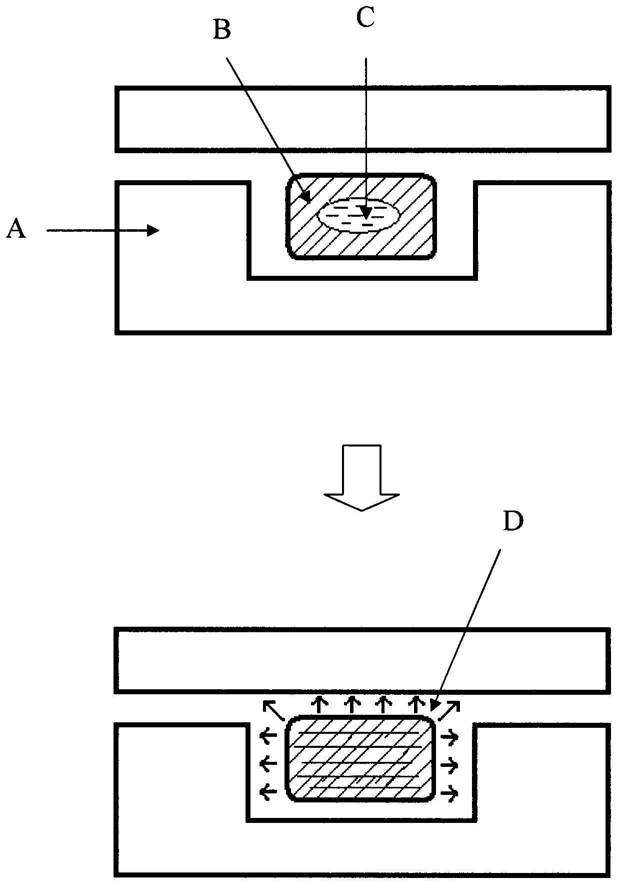
[0023] figure 1 A schematic diagram of the structure of the liquid storage part of a self-illuminating microfluidic chip provided by the present invention. A specific position in the microfluidic chip A has a larger liquid sac B filled with hydrogen peroxide solution; another smaller The liquid sac C is sealed in the liquid sac B, and the liquid sac C is filled with the mixed solution of fluorescent pigment and bisoxalate diester. When in use, depending on the external force, the liquid sac C is damaged, so that the liquid reagent stored in the liquid sac is released, and mixed with the reagent in the liquid sac B to undergo a chemical reaction, and the energy released in the chemical reaction is transferred to the fluorescent pigment molecules. Fluorescent pigments release energy in the form of visible light, thereby converting chemical energy into light energy D, and realizing the self-luminesc...

Embodiment 2

[0024] Example 2 A self-illuminating microfluidic chip with three liquid capsules

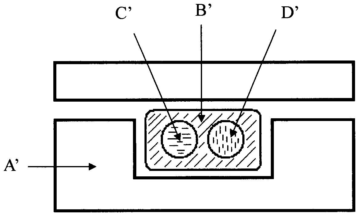
[0025] figure 2 It is a schematic structural diagram of the liquid storage part of a self-illuminating microfluidic chip provided by the present invention. A specific position in the microfluidic chip A' has a larger liquid sac B' filled with hydrogen peroxide solution; another The smaller sacs C' and D' are sealed in the sac B', C' is filled with fluorescent pigments, and D' is filled with bisoxalate diester solution. When in use, depending on the external force, the liquid sacs C' and D' are broken, so that the liquid reagent stored in the liquid sac is released and mixed with the reagent in the liquid sac B' to undergo a chemical reaction, and the energy released in the chemical reaction is transferred Give the fluorescent pigment molecules, and the fluorescent pigment releases energy in the form of visible light, thereby converting chemical energy into light energy and realizing the self-...

Embodiment 3

[0026] Example 3 A spontaneous microfluidic chip with side-by-side double liquid sacs

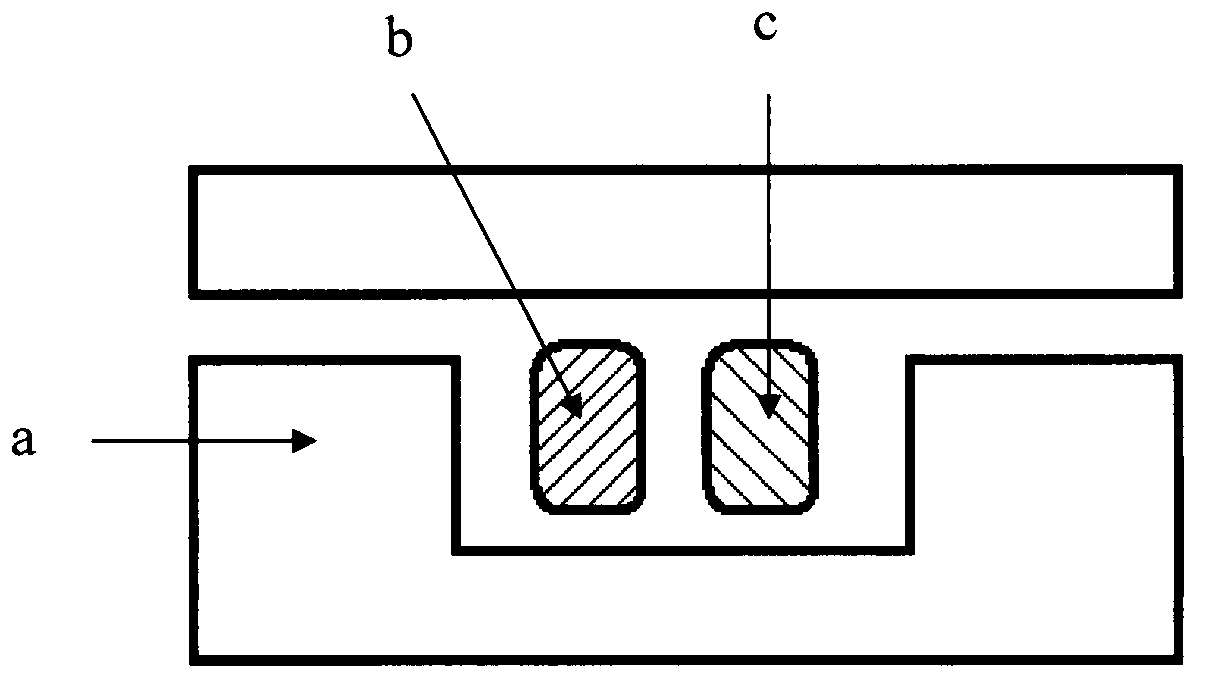
[0027] image 3 A schematic diagram of the structure of the liquid storage part of a self-illuminating microfluidic chip provided by the present invention, a specific position in the microfluidic chip a has a liquid capsule b filled with hydrogen peroxide solution, and another filled with fluorescent pigments and Liquid sac c of mixed solution of bis-oxalic acid diester. When in use, depending on the external force, the liquid sacs b and c are damaged at the same time, so that the two liquid reagents stored in the liquid sacs are released and mixed to undergo a chemical reaction, and the energy released in the chemical reaction is transferred to the fluorescent pigment molecules, and the fluorescent pigment with Energy is released in the form of visible light, thereby converting chemical energy into light energy and realizing the self-luminescence of the chip. Example 4 A spontaneous micr...


PUM


Abstract

The invention provides a self-luminescence type micro-fluidic chip which realizes self-luminescence by means of internally integrating a chemical reaction agent. The chemical reaction agent in the chip is stored at a specific part in the micro-fluidic chip in a sealed liquid bag or cavity, and is prepared from three substances, namely peroxides, an ester compound and fluorescent dye. According to the working principle of the self-luminescence type micro-fluidic chip, the liquid bag is broken under an external action so as to release the chemical agent stored in the bag, then the released chemical agent is subjected to mixing reaction, and therefore, chemical luminescence is realized. In the self-luminescence way, external light source devices and complicated control equipment are not required; and the micro-fluidic chip is simple and convenient to operate and especially applicable to a portable micro total analysis system.

Description

technical field [0001] The invention relates to a microfluidic chip, in particular to a self-illuminating microfluidic chip. Background technique [0002] In recent years, microfluidic chip technology has been widely researched and applied in the fields of biology, chemistry, and medicine. In the application process of microfluidic chips, many chemical and biological reactions and detections often need to be carried out under specific light source irradiation conditions. Therefore, light source control is of great significance in the application of microfluidic chips. [0003] At present, the light reaction or light detection of microfluidic chips is mainly realized by external light sources. However, this method has the following disadvantages: either additional equipment and energy consumption are required, or the preparation process is cumbersome and expensive. These shortcomings have affected the promotion of microfluidic chips, especially in some micro-total analysis...

Claims


Application Information

Patent Timeline
Patent Type & Authority Applications(China)
IPC IPC(8): B01L3/00
Inventor 叶嘉明
Owner 苏州扬清芯片科技有限公司
Why Eureka
Try Eureka