Method for preparing nanometer particles through electrochemistry discharging

A nanoparticle and electrochemical technology, applied in the direction of electrochemical processing equipment, manufacturing tools, metal processing equipment, etc., can solve the problems of high cost and low yield of nanoparticle preparation, and achieve strong operability, high yield, The effect of easy operation

Active Publication Date: 2013-08-21
江苏载驰科技股份有限公司
View PDF8 Cites 9 Cited by
  • Summary
  • Abstract
  • Description
  • Claims
  • Application Information

AI Technical Summary

Problems solved by technology

[0009] Aiming at the defects of high preparation cost and low yield of nanoparticles, t

Method used


Image

  • Method for preparing nanometer particles through electrochemistry discharging
  • Method for preparing nanometer particles through electrochemistry discharging

Examples


Embodiment 1

[0027] Silicon nanoparticles can be prepared by electrochemical discharge method.

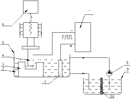
[0028] Choose to use as figure 2 The shown electrochemical discharge method can prepare silicon nanoparticles. 2 CO 3 solution, the workpiece material 3 used is intrinsic silicon, the tool electrode 4 used is a molybdenum rod, and the feed block selected is a graphite electrode.

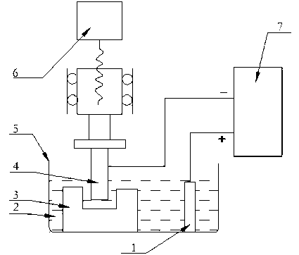
[0029] Add a pulse voltage with an amplitude of 100V, a frequency of 100Hz, and a duty cycle of 50% between the tool electrode 3 and the power supply block 1, so that hydrogen bubbles are continuously generated between the workpiece 3 and the tool electrode 4, and as the processing continues , the hydrogen bubbles completely wrap the tool electrode, completely isolate the tool electrode from the electrolyte, and form a potential difference. When the voltage reaches the voltage value required for the discharge, the hydrogen bubble layer is broken down, and the discharge is generated. The energy of the discharge is u...

Embodiment 2

[0033] PZT ceramic particles can be prepared by electrochemical discharge method.

[0034] Choose to use as figure 2 The electrochemical discharge method shown is a device for preparing PZT ceramic particles. First, add an electrolyte solution 2 with a concentration of 10% NaOH solution in the working solution tank 5. The workpiece material 3 used is PZT ceramics, and the tool electrode 4 used is molybdenum Rod, the selected power supply block is stainless steel.

[0035] A pulse voltage with an amplitude of 150V, a frequency of 100Hz, and a duty cycle of 50% is applied between the tool electrode 3 and the power supply block 1, so that hydrogen bubbles are continuously generated between the workpiece 3 and the tool electrode 4. , as the processing continues, the hydrogen bubbles completely wrap the tool electrode, completely isolate the tool electrode from the electrolyte, and form a potential difference. When the voltage reaches the voltage value required for the discharge,...


PUM

PropertyMeasurementUnit
Particle sizeaaaaaaaaaa

Abstract

The invention discloses a method for preparing nanometer particles through electrochemistry discharging, and belongs to the field of nanometer material preparation. During the process of preparing the nanometer particles, a tool electrode which is connected with a power source negative electrode and an electricity inlet block which is connected with a power source positive electrode undergo an electrochemistry reaction, bubbles are generated and the bubbles are attached on the surface of the tool electrode. As the preparation goes on, the part, below an electrolyte level, of the tool electrode is completely wrapped by the bubbles which are generated continuously, so that the tool electrode is completely isolated from an electrolyte, and therefore a voltage difference is formed between the tool electrode and the electrolyte. Then, a bubble layer of the tool electrode and a bubble layer of the surface of a workpiece are broken down to form a discharging channel, and discharging is conducted. Instantaneous high temperature and high pressure energy inside the discharging channel gasifies the electrolyte on the surface of the workpiece and then further smelts and gasifies the workpiece, corrosion-removing products are generated and dumped into the electrolyte, and the nanometer particles are formed after the products are cooled and solidified. The preparation method is low in cost and high in productivity.

Description

Technical field [0001] The present invention involves the field of nanomaterial preparation and specially involves a preparation method of nanoparticles. Background technique [0002] In nanoparticles, due to the effects of quantum restrictions, the energy -level atoms of the carrier have discontinuous energy -level structures.Due to the special energy -level structure, nanoparticles show unique physical properties, such as quantum size effects, quantum wearing effects, Kulun obstruction effects, surface quantum effects, quantum interference effects, multi -body -related and non -linear optical effects.It is of great significance for basic physics research and new electronics and optoelectric components.The growth of nanoparticle material growth and device application has always been one of the hot spots in the scientific community. [0003] Because nanoparticles have small size effects, surface and interface effects, quantum effects, macro quantum tunnel effects and catalytic ef...

Claims


Application Information

Patent Timeline
IPC IPC(8): B23H3/00
Inventor 张节周磊杰张伟汪炜朱文魁
Owner 江苏载驰科技股份有限公司
Why Eureka
Try Eureka