
Valve timing control apparatus for internal combustion engine

A control device and valve timing technology, which is applied in the direction of valve devices, valve details, mechanical equipment, etc., can solve problems such as decreased accuracy and unstable control of valve timing control devices

Inactive Publication Date: 2013-08-21
HITACHI AUTOMOTIVE SYST LTD
View PDF1 Cites 3 Cited by
  • Summary
  • Abstract
  • Description
  • Claims
  • Application Information

AI Technical Summary

Problems solved by technology

As a result, the accuracy of the gap between the driving balls and the ball grooves decreases, leading to destabilization of the control of the valve timing control device.

Method used


Image

  • Valve timing control apparatus for internal combustion engine
  • Valve timing control apparatus for internal combustion engine
  • Valve timing control apparatus for internal combustion engine

Examples


no. 2 approach 〕

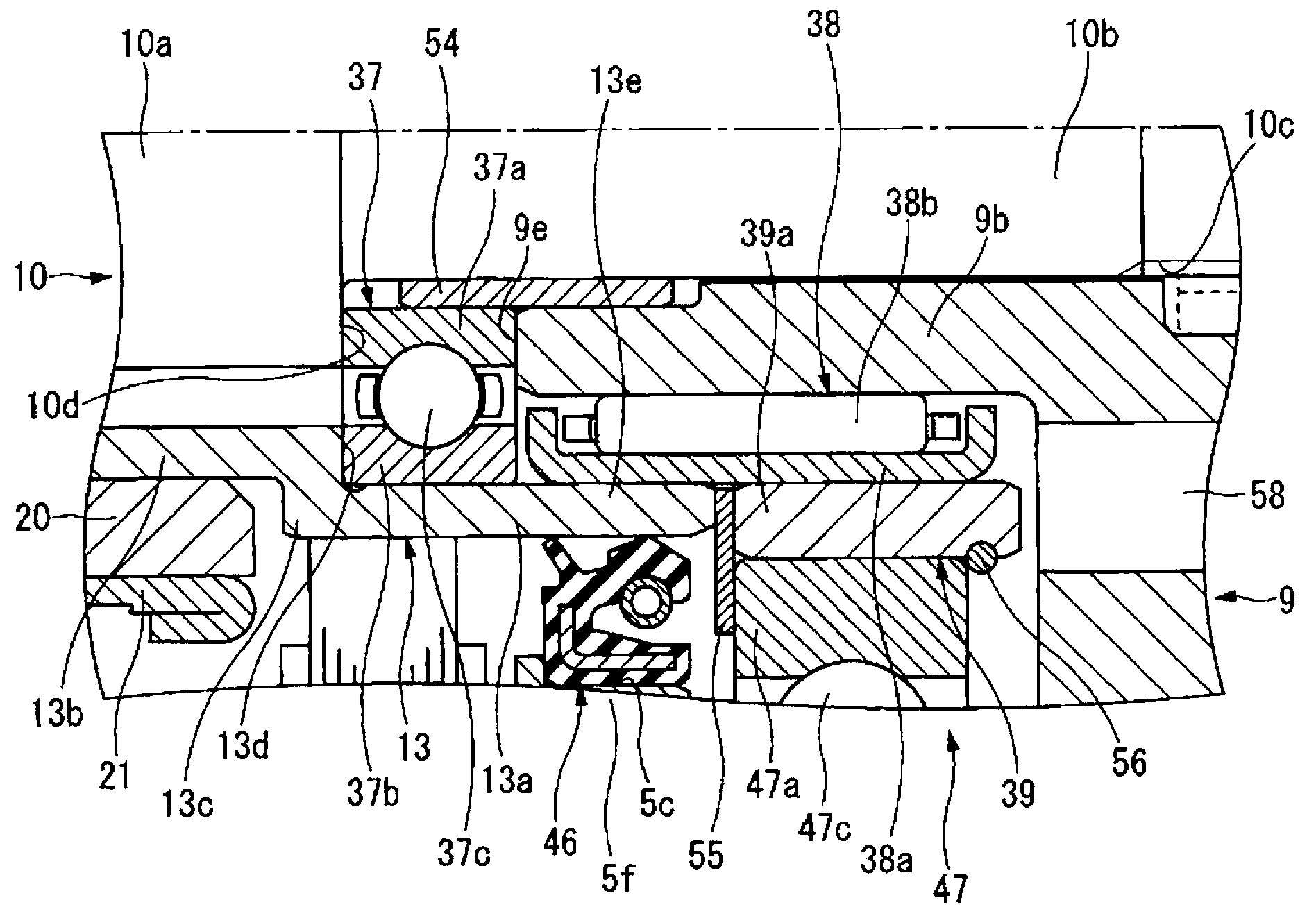
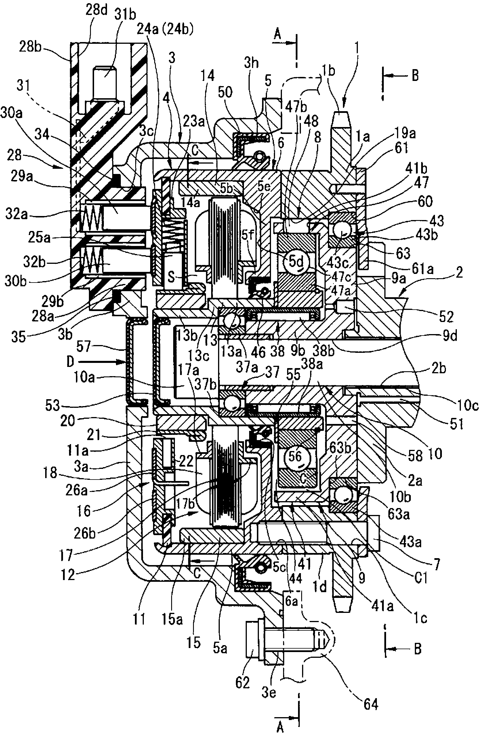
[0148] Figure 7 and Figure 8 In the second embodiment of the present invention, the thickness Q of the large-diameter portion 13 a of the motor shaft 13 is slightly larger than that of the small-diameter portion 13 b, and the axial length L is also increased by the thickness of the washer 55 .

[0149] Therefore, the inner peripheral side of the front end surface 13f of the large-diameter portion 13a abuts against the front end surface of the eccentric cam 39 from the axial direction, and the outer peripheral side of the front end surface 13f abuts against the side surface of the inner ring 47a of the ball bearing 47 through a step. catch. Therefore, axial movement of the inner ring 47a is restricted by cooperation of the front end surface 13f of the large-diameter portion 13a and the snap ring 56 .

[0150] Therefore, according to this embodiment, the washer 55 of the first embodiment can be eliminated, so that the number of parts can be reduced, and the manufacturing wor...

no. 3 approach 〕

[0153] Figure 9 The third embodiment is shown, and the outer diameter of the needle bearing 38 is formed larger than that of the first and second embodiments. In this case, the motor shaft 13 is formed with a The annular notch 13 g is formed slightly smaller than the thickness of the eccentric cam 39 .

[0154] In this way, by increasing the outer diameter of the needle bearing 38, the support rigidity of the motor shaft 13 and the eccentric cam 39 pressed into the outer peripheral surface is improved, and the bonding strength of both 13 and 39 is improved.

[0155] The other configurations are the same as those of the first embodiment, so the same effects can be obtained.

no. 4 approach 〕

[0157] Figure 10 The fourth embodiment is shown. Like the third embodiment, the outer diameter of the needle bearing 38 is formed larger, and the wall thickness Q and axial length L of the large-diameter portion 13a of the motor shaft 13 are set to be the same as those of the second embodiment. It is also larger, whereby the washer 55 can be eliminated and the support rigidity of the motor shaft 13 and the eccentric cam 39 can be increased.


PUM


Abstract

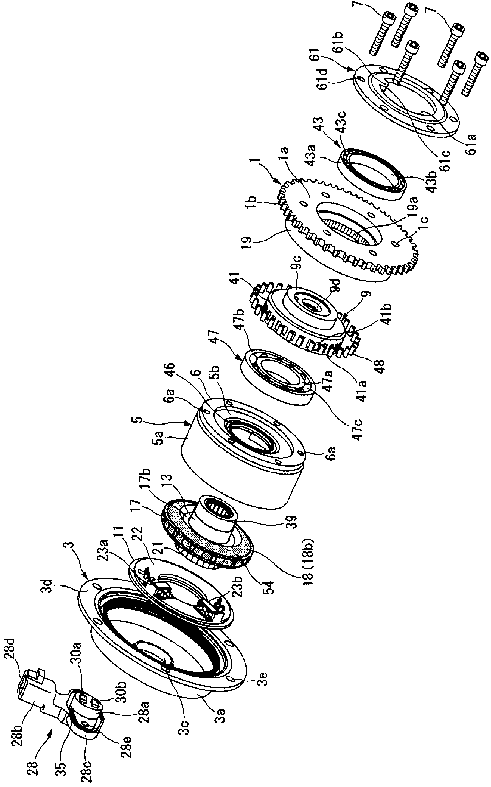
The invention provides a valve timing control apparatus for an internal combustion engine, and the valve timing control apparatus can integratlly conbine a motor output shaft and an eccentric cam by a bearing and prevent plastic deformation of of the eccentric cam. The valve timing control apparatus for the internal combustion engine comprises a retarding mechanism (8), and the retarding mechanism (8) is provided with a tube-shaped eccentric cam (39) whose outer periphery surface is eccentric relative to an axis, a plurality of rollers disposed between internal teeth and the eccentric cam, and a retainer maintaining comb state of each roller. The retainer rotates relative to the internal teeth through rotation of the eccentric cam. A tube-shaped motor shaft (13) which is fixed on inner periphery of an iron rotor is configured to connect in series with the eccentric cam. The whole eccentric cam and a major diameter (13a) of the motor shaft cross over in an axial direction and are pressed on an outer periphery surface of a retaining support (38a) of a needle bearing (38) which rotates on periphery of a cylinder portion (9b). The motor shaft and the eccentric cam are combined by the needle bearing.

Description

technical field [0001] The present invention relates to a valve timing control device for an internal combustion engine that controls the opening and closing timing of an intake valve and an exhaust valve that are engine valves of the internal combustion engine. Background technique [0002] In recent years, valve timing control devices have been provided that control the valve timing of intake valves and exhaust valves by changing the relative rotational phases of the crankshaft and camshaft by transmitting the rotational force of an electric motor to a camshaft via a reduction mechanism. control. [0003] It is well known that an alternating torque is generated on a camshaft of an internal combustion engine due to the spring force of a valve spring biasing an engine valve in a closing direction, or the like. [0004] For example, the speed reduction mechanism of the valve timing control device described in the following patent document 1 is provided with a cylindrical ecc...

Claims


Application Information

Patent Timeline
Patent Type & Authority Applications(China)
IPC IPC(8): F01L1/34
CPCF01L1/352F01L2250/02F01L2820/032F16C19/54
Inventor 田所亮小久保直树山中淳史川田真市
Owner HITACHI AUTOMOTIVE SYST LTD
Learn More