Micro-strip antenna facing optical and microwave coaxial detection application

A technology of microstrip antenna and microstrip feeder, which is applied in the direction of resonant antenna, antenna grounding device, antenna support/installation device, etc., to achieve the effects of enhanced mechanical stability, good directivity, and good resonance characteristics

Inactive Publication Date: 2013-08-21
HARBIN INST OF TECH
View PDF0 Cites 7 Cited by
  • Summary
  • Abstract
  • Description
  • Claims
  • Application Information

AI Technical Summary

Problems solved by technology

[0008] The purpose of the present invention is to solve the problem that the existing microstrip antenna is only used to receive and transmit electromagnetic waves, and is not combined with other disciplines, so as to realize the leap and combination betwee

Method used


Image

  • Micro-strip antenna facing optical and microwave coaxial detection application
  • Micro-strip antenna facing optical and microwave coaxial detection application
  • Micro-strip antenna facing optical and microwave coaxial detection application

Examples


specific Embodiment approach 1

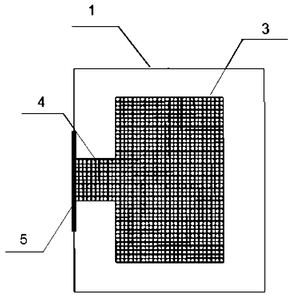
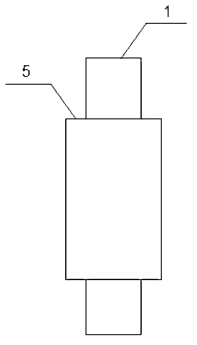
[0027] Specific implementation mode one: the following combination figure 1 , figure 2 and image 3 This embodiment is described. A microstrip antenna for optical and microwave coaxial detection applications described in this embodiment includes a transparent dielectric plate 1, a gridded ground plate 2, a gridded microstrip patch 3, and a grid Microstrip feeder 4 and waveguide port 5, the length and width of the transparent dielectric plate 1 and the gridded ground plate 2 are exactly the same, the length of the gridded microstrip patch 3 is shorter than the length of the transparent dielectric plate 1, and the grid The width of the gridded microstrip patch 3 is smaller than the width of the gridded microstrip patch 3, the width of the gridded microstrip feeder 4 is smaller than the width of the gridded microstrip patch 3, and the gridded ground plate 2 is completely covered On the lower surface of the transparent dielectric plate 1, the gridded microstrip patch 3 is appli...

specific Embodiment approach 2

[0028] Specific implementation mode two: the following combination figure 1 Describe this embodiment, this embodiment will further describe Embodiment 1, the length of the transparent medium plate 1 is 5 mm, the width is 4 mm, the thickness is 1 mm, the dielectric constant is 3.8, and the material of the transparent medium plate 1 is transparent Glass material.

specific Embodiment approach 3

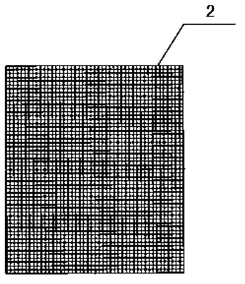
[0029] Specific implementation mode three: the following combination figure 2Describe this embodiment, this embodiment will further explain Embodiment 1, the length of the gridded ground plate 2 is 5mm, the width is 4mm, and the thickness is 0.0008mm, it is a copper metal coating, the gridded ground plate 2 It consists of 50*40 grids, each grid size is 0.1mm*0.1mm, the width of the metal coating between the grids is 0.01mm, and the duty ratio is 1:10.


PUM

PropertyMeasurementUnit
Lengthaaaaaaaaaa
Widthaaaaaaaaaa
Thicknessaaaaaaaaaa

Abstract

The invention relates to and discloses a micro-strip antenna facing an optical and microwave coaxial detection application. The micro-strip antenna solves the problem that an existing micro-strip antenna can not achieve optical detection while emitting and receiving an electromagnetic wave. The micro-strip antenna comprises a transparent medium plate, a rasterization earth plate, a rasterization micro-strip patch, a rasterization micro-strip feeder line and a wave guide port, wherein the rasterization earth plate is fully spread on the lower surface of the transparent medium plate, the rasterization micro-strip patch is spread on the upper surface of the transparent medium plate, the center of the transparent medium plate and the center of the rasterization micro-strip patch coincide, the wave guide port is fixed on the side face of the transparent medium plate and is located at the middle position of the long edge of the transparent medium plate, the rasterization micro-strip feeder line is spread on the upper surface of the transparent medium plate and located between the wave guide port and the rasterization micro-strip patch, feed electricity is transmitted to the rasterization micro-strip feeder line and the rasterization earth plate through the wave guide port, and the rasterization micro-strip feeder line transmits the received feed electricity to the rasterization micro-strip patch. The micro-strip antenna is used for the coaxial optical detection of the optical and microwave detection.

Description

technical field [0001] The invention relates to a microstrip antenna for optical and microwave coaxial detection applications. Background technique [0002] The microstrip antenna is a new type of antenna that has been gradually developed in the past 30 years. It is based on a thin dielectric substrate, with a thin metal layer attached on one side as a ground plane, and a metal patch of a certain shape is made on the other side by photolithography and other methods. , use the microstrip line and the axis to feed the patch to form a microstrip antenna. The microstrip antenna was originally used as a common omnidirectional antenna on rockets and missiles. With the development of material science and technology, the practical microstrip antenna has been greatly developed, and it is now available in a wide frequency band from about 100MHz to 50GHz. received a large number of applications. The emergence of the microstrip antenna is an important achievement in the application of...

Claims


Application Information

Patent Timeline
IPC IPC(8): H01Q9/04H01Q1/22H01Q1/38H01Q1/48
Inventor 杨国辉马爽张狂王二超
Owner HARBIN INST OF TECH
Why Eureka
Try Eureka