Steel strand prestress base structure of wind driven generator and construction method thereof

A technology for wind turbines and infrastructure, applied in infrastructure engineering, construction, etc., can solve the problems of excessive consumption of materials, reduced impact resistance, insufficient tensile force, etc. The effect of pull-out resistance

Inactive Publication Date: 2013-08-28
BEIJING HUADIAN XINNENG CONSULTATION
View PDF10 Cites 11 Cited by
  • Summary
  • Abstract
  • Description
  • Claims
  • Application Information

AI Technical Summary

Problems solved by technology

[0003]The disadvantages of the above-mentioned existing structure are: the diameter of the concrete base is 16-20m, and the area of ​​the hole needs to be large on the ground surface, and the vertical depth is 3m deep, so the engineering quantity is relatively large. In addition, the weight of the concrete base is 40-50t, 400-500m 3 , and the amount of steel bars is 40-60t, which consumes a lot of materials
The disadvantages of this structure are: since the long screw rods that mainly play the role of anti-pull are fixed on the lower flange of the connecting cylinder, and the size of the connecting cylinder corresponds to the bottom of the fan cylinder, the load of the long screw rod is very large. Easy to fatigue, it can be seen that the anchor rod foundation structure of this utility model is generally suitable for small wind turbines, and has strong limitations
The shortcomings of this structure are: its tensile strength is not enough, that is, the high-strength grouting column and the anchor rod of the utility model form a kind of friction pile instead of a load-bearing pile
Taking the cap platform with a diameter of 8m (100m 3 ) as an example, the depth of the straight hole is 15-20m, and the force required by each anchor is 200t (KN). In order to increase the toughness of the anchor, usually The reinforcement of the anchor rod needs to be heat treated; however, the toughness is indeed increased, but its impact resistance is greatly reduced; moreover, the biggest disadvantage of this kind of friction pile is that after long-term creep, a certain anchor rod may fail, which in turn leads to relative failure. The adjacent anchor rod fails, and even the entire wind turbine tower overturns

Method used


Image

  • Steel strand prestress base structure of wind driven generator and construction method thereof
  • Steel strand prestress base structure of wind driven generator and construction method thereof
  • Steel strand prestress base structure of wind driven generator and construction method thereof

Examples


Embodiment 1

[0055] Embodiment 1: The construction method of the basic structure of the present invention with a 1.5MW wind power generator installed (rock formation geological conditions).

[0056] (1) Dig a foundation pit with a diameter of 10m and a depth of 1.6m on the surface.

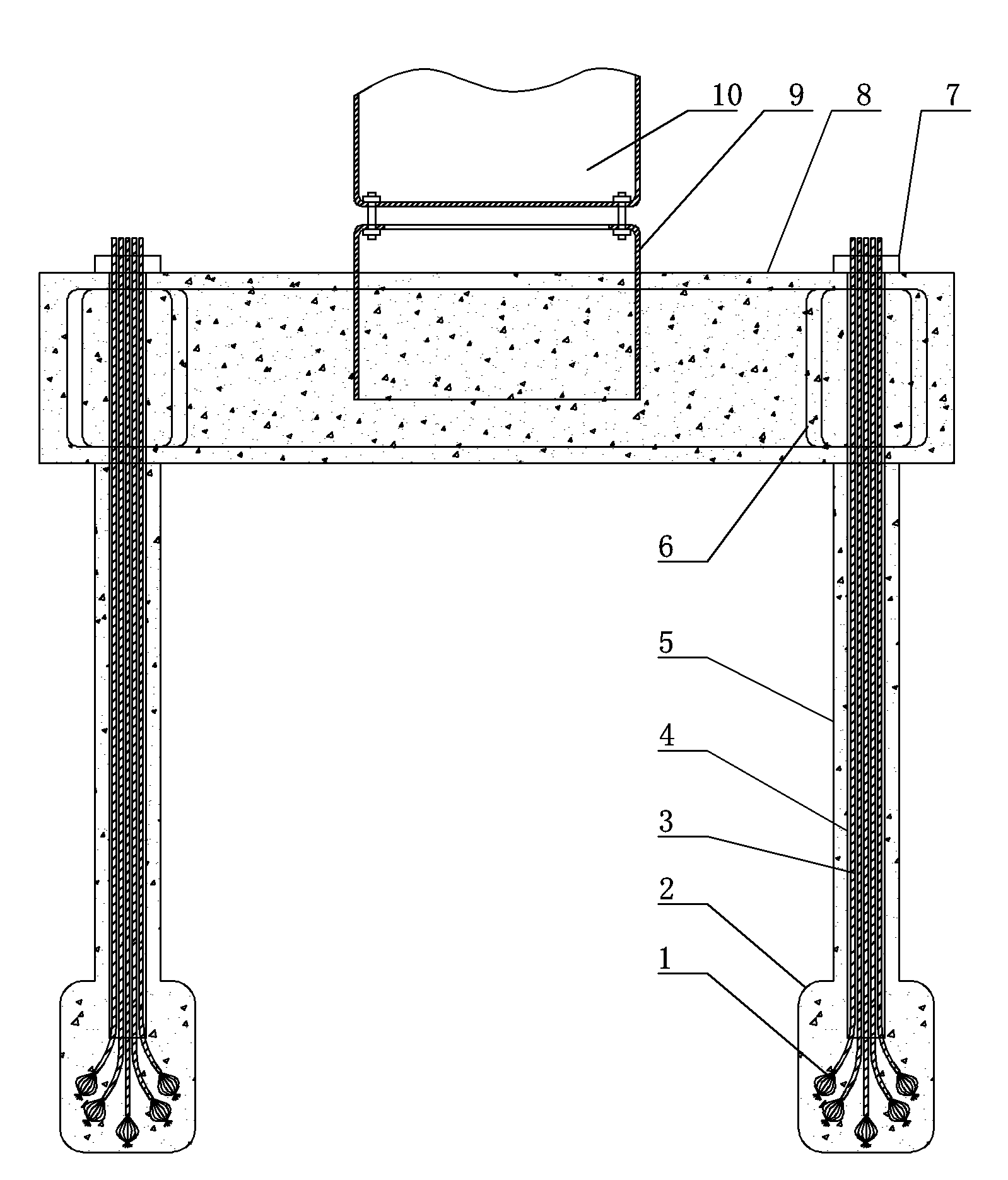
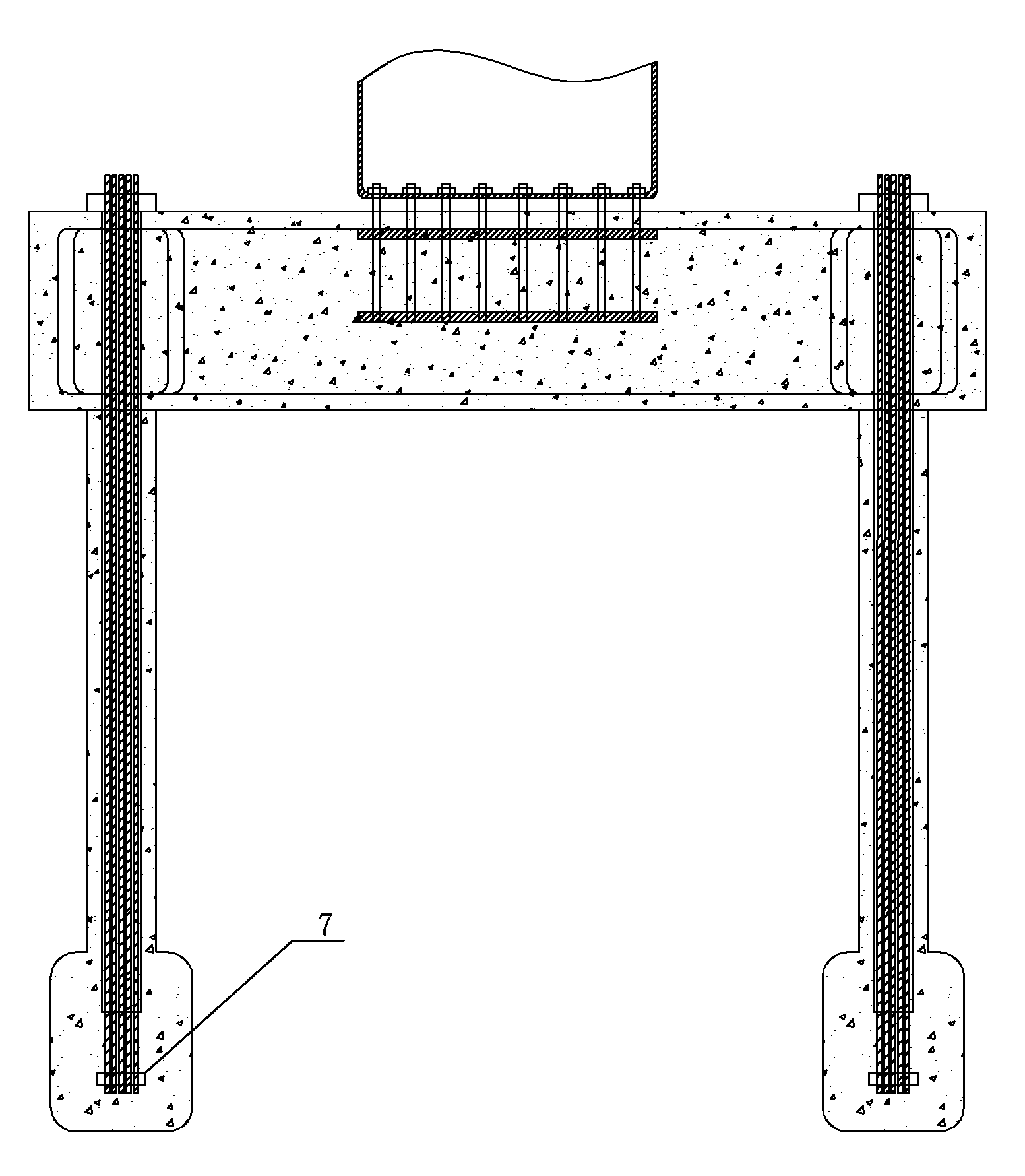
[0057] (2) At the bottom of the foundation pit along the circumference, two adjacent equidistant, drill straight holes 5 with a diameter of 150mm, a depth of 10m, and a number of 30. The distance between the center of the straight holes 5 and the center of the foundation pit is 4.5m .

[0058] (3) Use the reaming drill bit equipment to ream the bottom of the straight hole 5, the diameter of the reaming hole 2 is 250mm, and the height is 400mm.

[0059] (4) Drill a 200mm deep elongated hole 16 at the bottom of the reamed hole 2, and put a bamboo shoot 15 in the elongated hole 16, with a diameter of 140mm and a height of 300mm.

[0060] (5) Put steel strands 3 and 7 with metal embossing 1 at the bo...

Embodiment 2

[0068] Embodiment 2: The construction method of the basic structure of the present invention with a 2MW wind power generator installed (rock formation geological conditions).

[0069] (1) Dig a foundation pit with a diameter of 10m and a depth of 1.6m on the surface.

[0070] (2) At the bottom of the foundation pit along the circumference, two adjacent equidistant, drill straight holes 5 with a diameter of 150mm, a depth of 10m, and a number of 28. The distance between the center of the straight holes 5 and the center of the foundation pit is 4.5m .

[0071] (3) Use the reaming drill bit equipment to ream the bottom of the straight hole 5, the diameter of the reaming hole 2 is 250mm, and the height is 400mm.

[0072] (4) Drill a 200mm deep elongated hole 16 at the bottom of the reamed hole 2, and put a bamboo shoot 15 in the elongated hole 16, with a diameter of 140mm and a height of 300mm.

[0073] (5) Put 3 or 6 steel strands that have been tightened with posit...

Embodiment 3

[0081] Embodiment 3: The construction method of the basic structure of the present invention with a 2MW wind power generator installed (rock formation geological conditions).

[0082] (1) Dig a foundation pit with a diameter of 10m and a depth of 1.6m on the surface.

[0083] (2) At the bottom of the foundation pit along the circumference, two adjacent equidistant, drill straight holes 5 with a diameter of 150mm, a depth of 10m, and a number of 30. The distance between the center of the straight holes 5 and the center of the foundation pit is 4.5m .

[0084] (3) Use the reaming drill bit equipment to ream the bottom of the straight hole 5, the diameter of the reaming hole 2 is 250mm, and the height is 400mm.

[0085] (4) Drill a 200mm deep elongated hole 16 at the bottom of the reamed hole 2, and put a bamboo shoot 15 in the elongated hole 16, with a diameter of 140mm and a height of 300mm.

[0086] (5) Put steel strands 3 and 6 with metal embossing 1 at the botto...


PUM


Abstract

The invention provides a steel strand prestress base structure for a wind driven generator and a construction method thereof and relates to improvement of the rock layer and soil layer of base structure of the wind driven generator and the construction method thereof. The rock layer of base structure of the wind driven generator is stable and saves raw materials. The base structure comprises a concrete bearing platform, a fixing portion of the wind driven generator is arranged in the middle in the concrete bearing platform, the upper portion of the concrete bearing platform is connected with the bottom of a fan tower through bolts, straight holes are formed in the lower portion of the edge of the concrete bearing platform and evenly distributed on the circumference with the fixing portion as the center, the bottoms of the straight holes are communicated with bottom expanding holes under the straight holes, steel strands are arranged in the straight holes, anchoring portions of the steel strands arranged in the bottom expanding holes are arranged at the bottom ends of the steel strands, bellows are further arranged on the outside of the steel strands, pouring concrete is arranged in places between the bellows and the straight holes and in the bottom expanding holes, concrete is arranged in the bellows and gaps between the steel strands, and the upper ends of the steel strands are fixed on the concrete bearing platform through a location anchoring disc.

Description

Technical field [0001] The present invention is the field of wind power technology. More specifically, it is the improvement of a wind turbine rock layer and soil layer infrastructure, and its construction methods. Background technique [0002] The existing wind turbine infrastructure is usually the following structure: (see Figure 9 ) Set up a cone concrete base with a diameter of 16 to 20m and a depth of about 3m under the surface. 3 , The amount of steel bars is 40 to 60T; the middle of the concrete base has a cylindrical metal ring. The top of the metal ring is flange.The other parts are buried in the concrete with the inserted steel bars. [0003] The disadvantages of the above existing structure are: the diameter of its concrete base is 16-20m, and the area of the open hole on the surface needs to be large, the vertical depth is 3m deep, so the amount of project is large; in addition, the weight of the concrete base is 40-50T, 400 ~500M 3 , The amount of reinforcement i...

Claims


Application Information

Patent Timeline
Patent Type & Authority Applications(China)
IPC IPC(8): E02D27/44
Inventor 孟庆波
Owner BEIJING HUADIAN XINNENG CONSULTATION
Why Eureka
Try Eureka