
Vertical worm and worm gear mechanism with self-lubricating function

A technology of worm gear and worm gear, which is applied in the direction of gear lubrication/cooling, mechanical equipment, belt/chain/gear, etc. It can solve the problems of increasing the production and application cost of the reducer, not easy to process deep holes, and large oil churning loss, etc., to achieve improved Transmission efficiency, installation flexibility, simple structure and reliable operation

Inactive Publication Date: 2015-05-20
NANJING UNIV OF AERONAUTICS & ASTRONAUTICS
View PDF6 Cites 0 Cited by
  • Summary
  • Abstract
  • Description
  • Claims
  • Application Information

AI Technical Summary

Problems solved by technology

In Chinese Invention Patent No. 200710035077.2, a worm gear with dynamic and static pressure lubrication in the meshing area is disclosed by arranging labyrinth teeth on the outside of the worm and helical blades on the end face, which can form a good lubricating oil film on the friction surface, but this method For a worm gear reducer that works for a long time, it is easy to cause serious heating of the oil and a large oil churning loss; Chinese utility model patent No. 201120360481.9 discloses a vertical worm gear that uses an additional oil pump to spray oil to the friction surface The worm lubrication method better solves the lubrication and friction heating problems of the vertical worm gear transmission, but the pressure generated by the oil injection on the oil inside the reducer will cause oil leakage. At the same time, the additional oil pump greatly increases the speed of the reducer. The production and application cost is low, and it is not easy to process deep holes in the middle of the worm

Method used


Image

  • Vertical worm and worm gear mechanism with self-lubricating function
  • Vertical worm and worm gear mechanism with self-lubricating function
  • Vertical worm and worm gear mechanism with self-lubricating function

Examples


Embodiment Construction

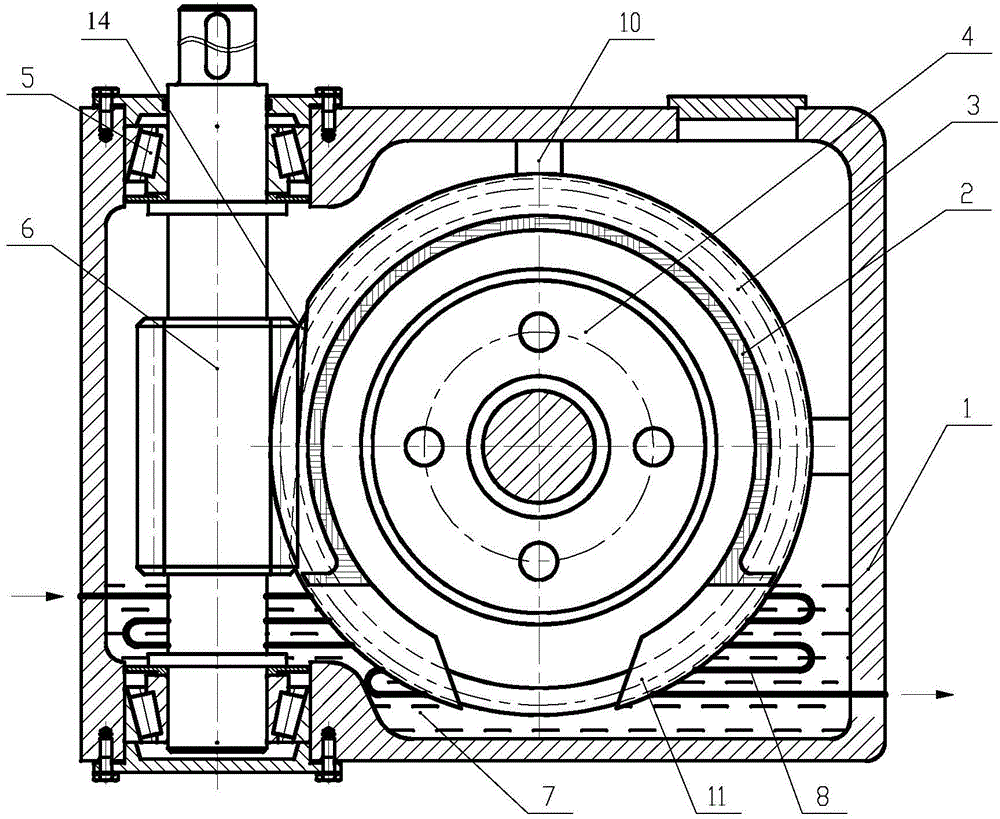
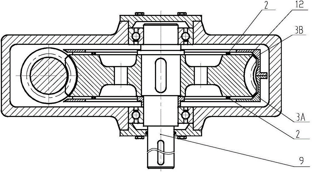
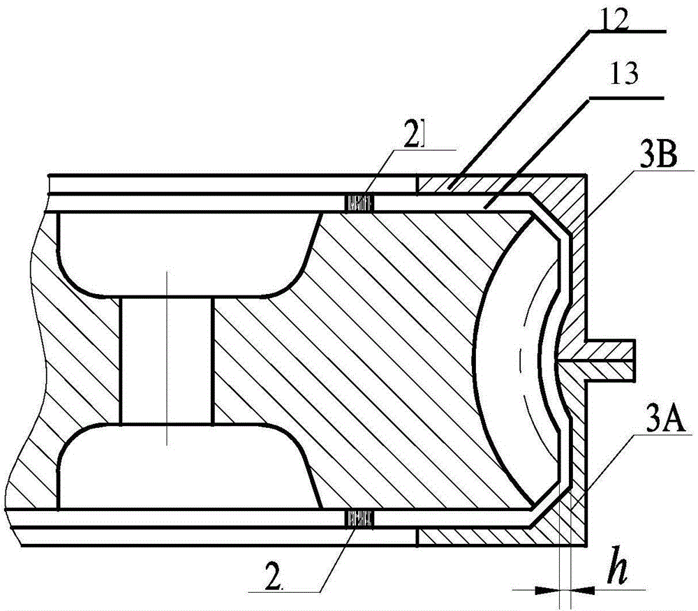
[0012] see figure 1 and figure 2 As shown, the present invention discloses a vertical worm gear mechanism with self-lubricating function, which includes a box body 1, a worm wheel 4 and a worm screw 6 installed in the box body 1 and intermeshing with each other, and the worm screw 6 is vertically arranged in the box body Body 1. An oil scraper cover 3 covering the outer edge of the worm wheel 4 is also provided, and the oil scraper cover 3 includes an inlet 11 at the bottom, side walls 12 covering both sides of the outer edge of the worm wheel 4; the two side walls 12 A seal 2 is interposed between the worm wheel 4 and an oil inlet channel 13 is formed between the side wall 12, the seal 2 and the worm wheel 4. One side of the oil inlet channel 13 communicates with the inlet 11 and the other The side communicates with the meshing part of the worm gear. Both end faces of the worm gear 4 and the oil scraper cover 3 are fitted with seals 2, thereby preventing the leakage of th...


PUM


Abstract

The invention provides a vertical worm and worm gear mechanism with a self-lubricating function. The mechanism mainly comprises a worm gear, a worm, an oil scraping cover, a special-shaped sealing element and the like. The worm gear matches with the oil scraping cover in movement to drive oil from the bottom to a worm and worm gear meshing area, so that meshing surfaces are lubricated and cooled sufficiently. Boundary conditions of leakage caused by shear flow under oil differential pressure are computed to obtain a reasonable matching range between the worm gear and the oil scraping cover. The vertical worm and worm gear mechanism with the self-lubricating function is simple in structure, reliable in working and suitable for long-time operation, and transmission efficiency and mounting and use flexibility of a worm and worm gear reducer are improved greatly.

Description

technical field [0001] The invention relates to a worm gear mechanism, in particular to a vertical worm gear mechanism. Background technique [0002] Worm gear transmission is used to transmit motion and power between interlaced shafts. It has the advantages of large transmission ratio, compact structure, stable transmission and self-locking, but its own low transmission efficiency (generally only 0.7 to 0.9) makes the application subject to At the same time, its transmission heat is large, the tooth surface is easy to wear, etc., which put forward higher requirements on the processing technology and material selection of the worm gear. For the former, it is mainly improved by studying the structural parameters of the worm gear itself. For the latter The latter is mainly improved by improving the transmission lubrication method. At present, the lubrication of worm gear transmission can be divided into two types: 1. Oil pool lubrication, which is suitable for horizontal worm...

Claims


Application Information

Patent Timeline
Patent Type & Authority Patents(China)
IPC IPC(8): F16H57/04F16H57/039
Inventor 李成刚夏玉辉张文妍游有鹏王化明陈柏吴洪涛缪群华朱玉川
Owner NANJING UNIV OF AERONAUTICS & ASTRONAUTICS
Learn More