
Non-contact type mechanical sealing device

A mechanical sealing device, non-contact technology, applied in the direction of engine sealing, mechanical equipment, engine components, etc., can solve the problem that the seal end face gap cannot be adjusted actively, achieve a wide range of speed adaptation, reduce maintenance costs, and low power consumption Effect

Inactive Publication Date: 2013-08-28
XIHUA UNIV
View PDF16 Cites 6 Cited by
  • Summary
  • Abstract
  • Description
  • Claims
  • Application Information

AI Technical Summary

Problems solved by technology

There are two problems in the traditional fluid film non-contact mechanical seal: one is that it is impossible to actively adjust the seal end face clearance
However, the traditional non-contact mechanical seal is still difficult to meet the above requirements, and new mechanical seal devices must be researched and developed to meet the needs of industrial production and special circumstances.

Method used


Image

  • Non-contact type mechanical sealing device
  • Non-contact type mechanical sealing device
  • Non-contact type mechanical sealing device

Examples


Embodiment Construction

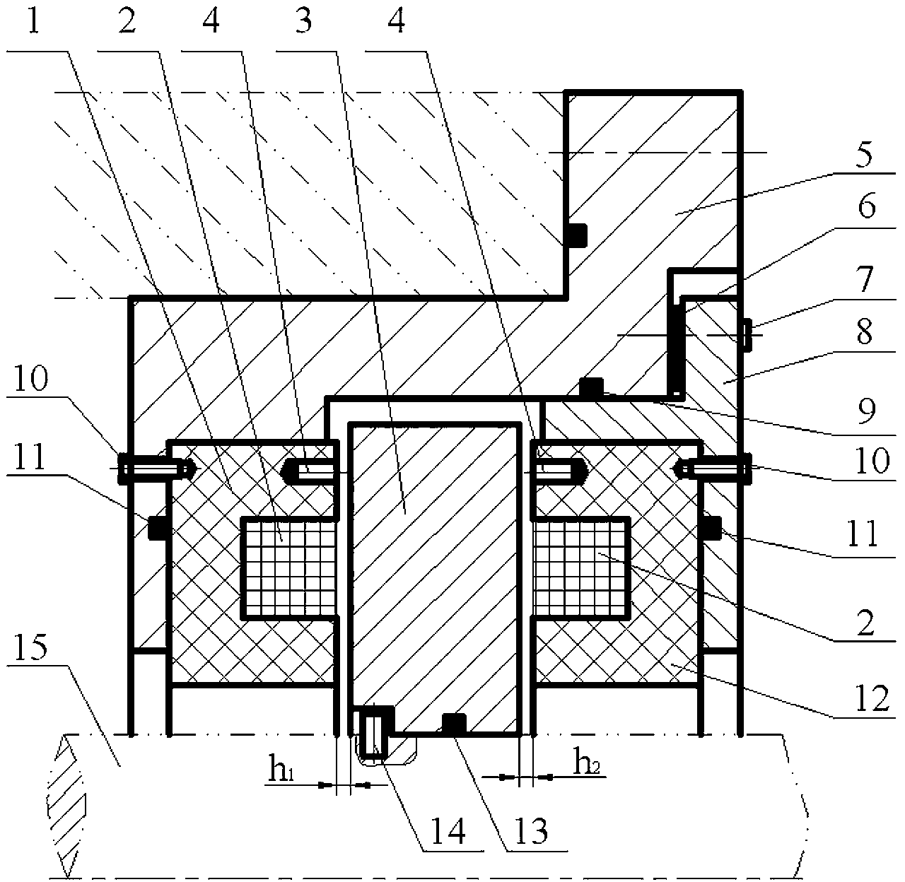
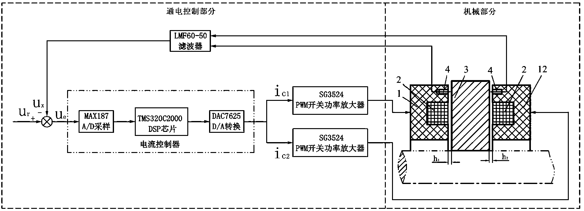
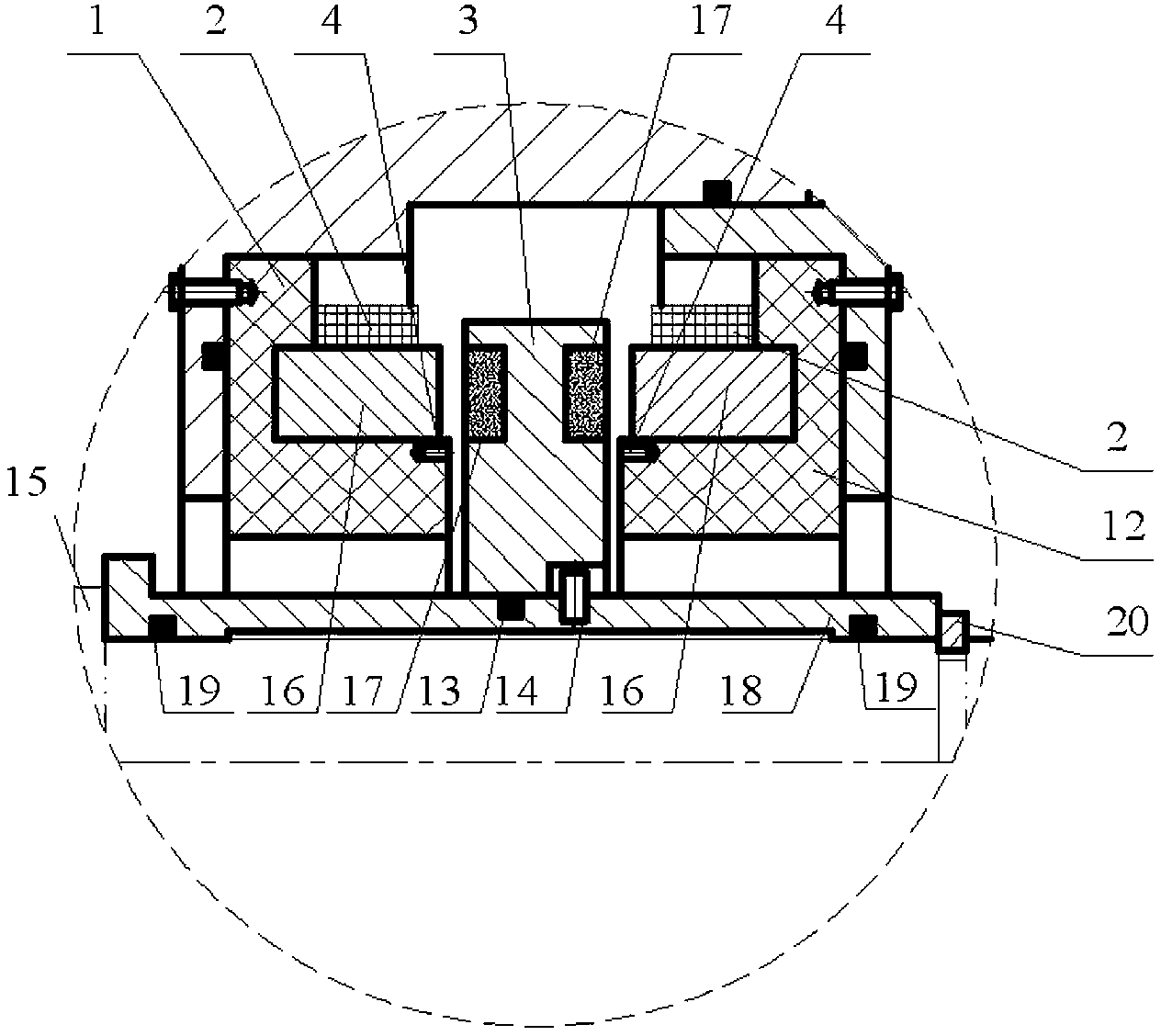
[0027] Such as figure 1 As shown, the structure of the non-contact mechanical seal device includes seal ring 1 and seal ring 12, coil 2, seal ring 3, sensor 4, stationary ring seat 5, gasket 6, screw 7, end cover 8, seal Ring 9, screw 10, static sealing ring 11, dynamic sealing ring 13, transmission pin 14 and other structures. figure 1 The sealing ring 3 in the figure is a rotating sealing ring arranged in the first sealing unit; the sealing ring 1 and the sealing ring 12 are stationary sealing rings respectively arranged in the second sealing unit.

[0028] The sealing ring 3 made of commonly used ferromagnetic materials such as silicon steel or iron-nickel alloy is directly connected with the rotary shaft 15 of the unit in a circumferentially fixed transmission connection with the pin 14 and the groove with the axial displacement gap allowed by the design, so that the sealing The ring 3 can rotate with the rotating shaft 15 during operation, and can also move axially b...


PUM


Abstract

The invention discloses a non-contact type mechanical sealing device. A rotating sealing ring and a static sealing ring are coaxially arranged, and sealing is achieved through the axial end surface of the rotating sealing ring and the axial end surface of the static sealing ring. A sealing ring structural body of a first sealing unit comprises a sealing ring and a ferromagnetic material structure or a permanent magnet material structure, wherein the sealing ring can make axial displacement, and both two axial end surfaces of the sealing ring are sealing surfaces. A second sealing unit comprises two sealing structural bodies which are axially arranged at two axial ends of the sealing ring structural body of the first sealing unit, a sealing ring and a corresponding electromagnet structure are arranged on each sealing ring structural body of the second sealing unit in a sealing clearance mode, and each sealing ring and each electromagnet structure are opposite to the axis of the sealing ring of the first sealing unit. When one sealing ring of the two sealing units is the rotating sealing ring, the sealing ring of the other sealing unit is the static sealing ring. A sensing structure which detects the distance between the sealing clearances is arranged on at least one side of the two sealing structural bodies which are opposite to the sealing clearances, and an electromagnetic coil and the sensing structure of each electromagnet structure are respectively connected with an energizing control structure. The non-contact type mechanical sealing device can achieve active control of the sealing clearances in a magnetic levitation mode, enables the sealing to have a good dynamic property, and is reliable and stable in operation, easy to maintain, long in service life and wide in application range.

Description

technical field [0001] The invention relates to a non-contact mechanical seal device, more particularly to a non-contact mechanical seal device working in a magnetic levitation mode. Background technique [0002] The fluid film non-contact mechanical seal is a commonly used shaft end seal method at present, and the seal is realized by a rotating seal ring and a stationary seal ring coaxially arranged with the opposite end faces as the sealing faces. The rotating sealing ring can rotate with the rotating shaft, and the stationary sealing ring is positioned and connected with the corresponding fixed structure on the machine base. When the unit is running, under the fluid friction state, a complete fluid film is filled between the sealing end faces to make the rotating ring and the stationary ring separate from each other and achieve a dynamic seal. One of the main directions of non-contact mechanical seal research today is to improve the stability and reliability of seal oper...

Claims


Application Information

Patent Timeline
IPC IPC(8): F16J15/53
CPCF16J15/3444
Inventor 王和顺朱维兵董霖胡俊
Owner XIHUA UNIV
Learn More