Power generating device for rolling roads and array thereof

A technology for power generation devices and highways, applied in electromechanical devices, generators/motors, piezoelectric effect/electrostrictive or magnetostrictive motors, etc., can solve the problems of high cost, difficult maintenance, complex structure, etc. Simple structure, few parts and high reliability

Active Publication Date: 2013-08-28
高通环保科技股份有限公司
View PDF8 Cites 7 Cited by
  • Summary
  • Abstract
  • Description
  • Claims
  • Application Information

AI Technical Summary

Problems solved by technology

[0004] In order to overcome the technical defects of the prior art roller compaction power conversion device with complex structure

Method used


Image

  • Power generating device for rolling roads and array thereof
  • Power generating device for rolling roads and array thereof
  • Power generating device for rolling roads and array thereof

Examples


Embodiment Construction

[0023] The specific embodiment of the present invention will be further described in detail below in conjunction with the accompanying drawings.

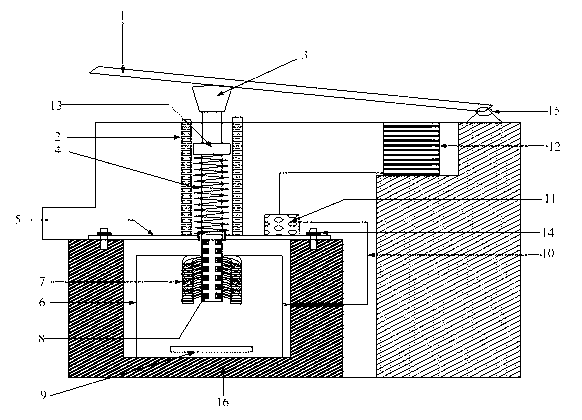
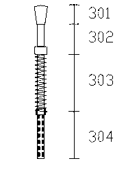
[0024] The road rolling power generation device disclosed in the present invention includes a movable cover plate 1 and a central shaft 3 located below the movable cover plate, such as figure 2 As shown, the central axis is divided into a pressure-bearing section 302, a deformation section 303 and a power generation section 304 from top to bottom. The power generation section 304 is wound with a conductive coil 8, and the deformation section 303 is covered with a spring 4. The connection between the deformation section 303 and the pressure section 302 has a positioning section 13 larger than the outer diameter of the spring; it also includes a fixed plate 5, and the fixed plate 5 has a through hole with a diameter smaller than the outer diameter of the spring but larger than the outer diameter of the power generation section. The p...


PUM


Abstract

The invention discloses a power generating device for rolling roads. The power generating device comprises a movable cover plate and a central shaft connected with the movable cover plate, wherein the central shaft is divided into a bearing section, a deformation section and a power generating section in sequence from top to bottom; the bearing section is connected with the movable cover plate; the power generating section is wound with conducting coils; a spring is sheathed on the deformation section; the connecting part between the deformation section and the bearing section is provided with a positioning joint larger than the outer diameter of the spring. The power generating device also comprises a fixed plate, wherein the fixed plate is provided with a penetrating hole with the diameter less than the outer diameter of the spring but more than the outer diameter of the power generating section, and the power generating section penetrates through the penetrating hole; a magnetic-permeable body surrounding the power generating section is arranged in the space under the fixed plate; and the central axis of the magnetic-permeable body is coincided to the central axis of the penetrating hole. The invention also discloses an array of the power generating device for rolling the roads. The power generating device and the array disclosed by the invention have the advantages that charges are generated by utilizing the displacement of the central axis along the vertical direction, and the central axis is returned by utilizing the spring; and the structure is simple, the parts are fewer and the reliability is high.

Description

technical field [0001] The invention belongs to the field of energy, and relates to a power generation device, in particular to a road rolling power generation device and an array thereof. Background technique [0002] As the energy crisis intensifies, the voice of low-carbon economy is getting higher and higher, and people pay more and more attention to energy efficiency. The continuous flow of vehicles passing the road all day long will deform and vibrate the road under the pressure of the vehicles. This energy is huge. If it can be converted into electrical energy to power signal lights, toll stations, parking lots and even residents, it will inevitably save a lot of electrical energy. , improve energy utilization, reduce air pollution caused by thermal power generation and water pollution caused by hydropower generation, and in remote areas, it can also save electricity transmission costs and create more economic benefits. [0003] Vehicle rolling power generation devic...

Claims


Application Information

Patent Timeline
IPC IPC(8): H02K35/04H02N2/18
Inventor 胡登燕
Owner 高通环保科技股份有限公司
Why Eureka
Try Eureka