Intervertebral medical implant

一种医学植入体、植入体的技术,应用在医学植入体领域,能够解决牢固性低等问题,达到高稳定性的效果

Inactive Publication Date: 2013-08-28
ACES
View PDF17 Cites 0 Cited by
  • Summary
  • Abstract
  • Description
  • Claims
  • Application Information

AI Technical Summary

Problems solved by technology

When bone graft materials are used as implant materials, the low firmness of these materials prevents the manufacture and application of this tooth-like geometry

Method used


Image

  • Intervertebral medical implant
  • Intervertebral medical implant
  • Intervertebral medical implant

Examples


Embodiment 5

[0048] Example 5e describes another variant of the intervertebral disc implant ( Figure 10 ). Variant 5e consists of a plurality of plates which are arranged alternately with respect to the upper plate 501 and the lower plate 502 . A feature of this embodiment is the combination of a container 5050 having at least one lateral opening 571 . Through this opening 571 a penetrating bone anchor 572 is introduced into the vertebral body and connected to the bone 1 . This example 5e therefore provides better initial stability. Furthermore, embodiment 5e has three eccentric shafts 5051 , 5052 and 5053 , which are supported at the front 5050 and rear 5054 positions and axially positioned by the snap ring 5012 . Depending on the shape and position of the cam, various biomechanically important properties can be tuned. For example, the embodiment 5e shown here provides an implant that can expand laterally as well as in height through selected incisions 5011,5012,5013.

[0049] Varia...


PUM


Abstract

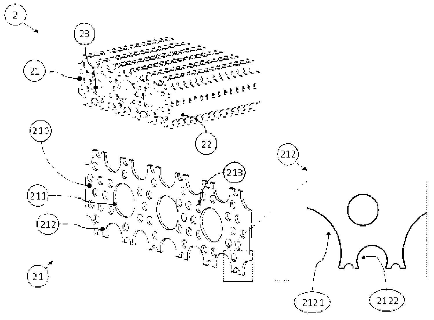
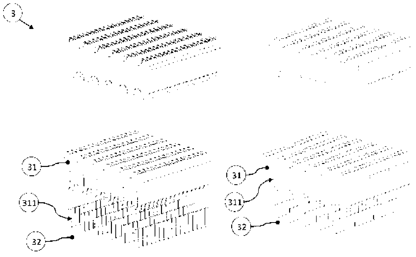
The fusion of two vertebrae is one of the most common procedures in spinal surgery. The invention relates to a spinal implant composed of a plurality of parallel plates. The deliberate introduction of contours in the plates allows for the creation of biomechanically advantageous functions and adjustment options that cannot be provided in any other manner or only at a high cost. The elasticity of the anchoring elements enables the disclosed implant to be adjusted to the osseous endplates, resulting in uniform force distribution and thus prevention of the risk of compaction or endplate compression fracture. The plate structure allows for the use of production methods in which hook-like undercut contours can be created, thus enabling the implant to be superbly anchored in the bone without causing damage thereto.; Furthermore, the plates can be interconnected by an actuator in such a way that the height and / or the angular position can be adjusted, thus enabling the intervertebral disk space to be vertically and physically adjusted. The vertical adjustment can vary along the length of the implant such that the segment can also be angularly adjusted. If the plates are interconnected by an eccentric shaft, the combined vertical and translational movement to which the set of plates is subjected can also be used to translationally reposition two vertebrae.

Description

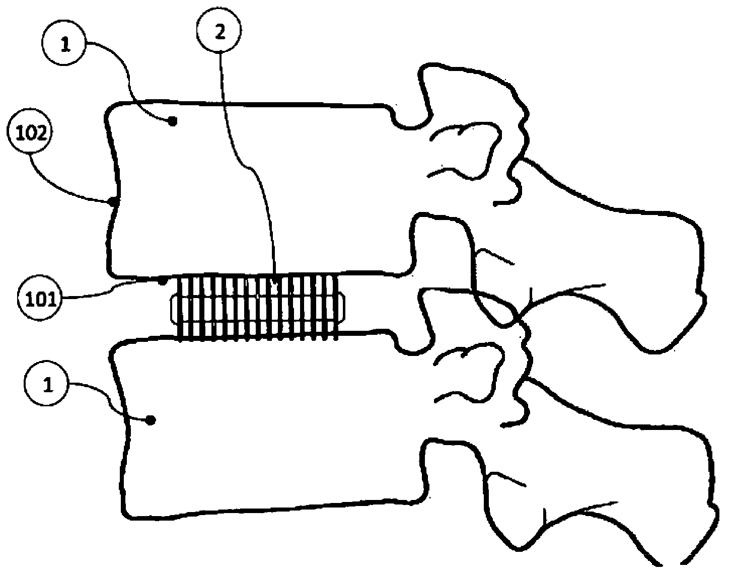
technical field [0001] The present invention relates to a medical implant inserted into the intervertebral space of two vertebrae to stabilize the spine. An essential feature of the implant according to the invention is that said implant is composed of a plurality of thin plates, allowing further superior properties of manufacture, implantation and in vivo function. Background technique [0002] When a spinal lesion occurs, it is often necessary to stabilize one or more segments of the spine. As a result, there are now a variety of intervertebral implants (also known as "intervertebral cages") on the market, the purpose of which is to create bony fusion of a portion of the spine. The implantation of such intervertebral fusion cages is associated with many complicating factors. Examples include endplate compression fractures due to local stress applied or due to the small area in which the implant is placed, intended bony fusion not being successfully achieved due to stress...

Claims


Application Information

Patent Timeline
Patent Type & Authority Applications(China)
IPC IPC(8): A61F2/44A61L27/50A61L27/56
CPCA61F2/30942A61F2/442A61F2/4455A61F2/447A61F2002/30322A61F2002/30433A61F2002/30517A61F2002/30553A61F2002/30556A61F2002/30563A61F2002/30576A61F2002/30579A61F2002/30593A61F2002/30594A61F2002/30601A61F2002/30604A61F2002/30616A61F2002/30622A61F2002/30668A61F2002/30736A61F2002/30784A61F2002/30892A61F2002/30904A61F2002/3092A61F2002/30925A61F2002/3093A61F2002/3097A61F2002/30971A61F2002/30976A61F2002/30978A61F2002/448A61L27/04A61L27/14A61L2430/38A61F2/482
Inventor 弗兰克·特劳特韦恩弗兰克·霍耶尔约尔格·弗兰卡拉尔夫·科特乌尔夫·利尔恩奎斯特盖伊·麦蒂戈迈克尔·普奇尔
Owner ACES
Why Eureka
Try Eureka