Battery electrode coating device

A technology for coating devices and battery pole pieces, which is applied to devices and coatings that apply liquid to the surface. Work efficiency and product quality, uniform coating thickness, and uniform spacing

Active Publication Date: 2013-09-04
LANS INTELLIGENT ROBOT CHANGSHA CO LTD
View PDF8 Cites 3 Cited by
  • Summary
  • Abstract
  • Description
  • Claims
  • Application Information

AI Technical Summary

Problems solved by technology

At present, there are the following blanking methods: 1. Scraper blanking, 2. Rolling and back rolling separation blanking, 3. Squeezing blanking. These blanking methods have the following disadvantages: 1. There is a serious tailing phenomenon, 2. The distance between the blank space is too long, which wastes materials. 3. The thickness of the blank space is uneven, which affects the quality of battery products
But, in the coating process, the rotating speed of coating roller 1 and backing roller 2 is constant, and in the two processes of coating slurry 4 and reserving blank belt 6 again, the rotating speed of coating roller 1 and backing roller 2 is constant. Therefore, at the moment when the current collector 5 on the coating roller 1 and the back roller 2 is just in contact, the relative speed is relatively high, which will cause a "smearing" phenomenon on the pole piece, that is, the blank belt 6 on the pole piece is initially coated with slurry The slurry at the material is thicker, forming protrusions, such as attached figure 2 The "tailing" phenomenon occurs at A
In the process of compacting the pole piece with a trailing roller, the trailing part is subjected to a large force and often loses material
In addition, during the process of stacking or winding the pole pieces, the trailing part is very easy to drop

Method used


Image

  • Battery electrode coating device
  • Battery electrode coating device
  • Battery electrode coating device

Examples


Embodiment Construction

[0019] In order to facilitate the understanding of those skilled in the art, the present invention will be further described below in conjunction with the accompanying drawings.

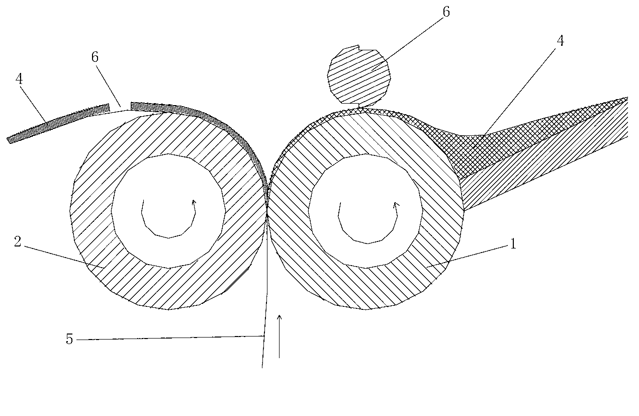
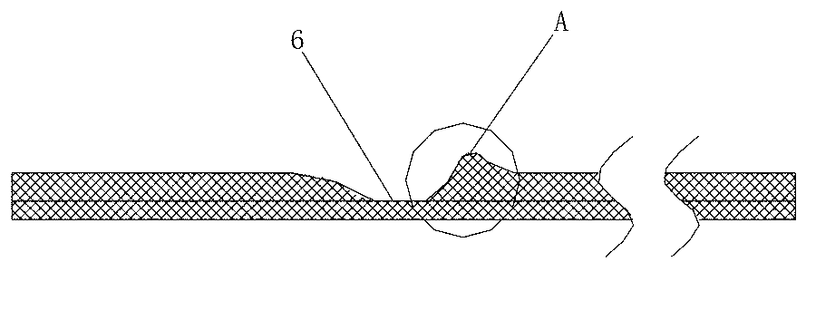
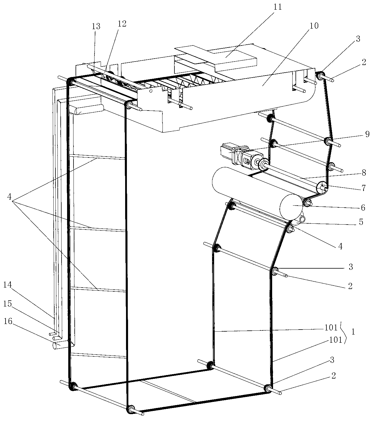
[0020] as attached image 3 As shown, the present invention discloses a coating device for battery pole pieces, including a coating roller 6 and a back roller 5, and the coating device also includes a conveyor belt group 1, a driver 9 and several driven shafts with driven wheels 3 2. The driver 9 is connected with the main transmission shaft 8, the main transmission shaft 8 is equipped with the driving wheel 7, the conveyor belt group 1 is set on the driving wheel 7 and the driven wheel 3 and passes between the coating roller 6 and the back roller 5 to form a In a closed loop, a blank spacer belt 4 is fixedly installed in the conveyor belt group 1, and at least one blank spacer belt 4 is installed. When there are a plurality of blank spacers 4, each blank spacer 4 is evenly or unevenly spaced on the...


PUM


Abstract

The invention discloses a battery electrode coating device which comprises a coating roll, a backup roll, a conveyor belt group, a driver, and a plurality of driven shafts provided with driven wheels, wherein the driver is equipped with a main driving shaft sleeved with a driving wheel; the conveyor belt group is mounted on the driving wheel and the driven wheels in a sleeving manner and passes through the coating roll and the backup roll to form a closed circulation loop; at least one spacer isolation belt is fixedly mounted between the conveyor belt group which comprises two conveyor belts parallelly arranged at an interval; the spacer isolation belt spans and is mounted on the two conveyor belts in a direction perpendicular to the two conveyor belts; and each conveyor belts is mounted on the corresponding driven wheels and the driving wheel in a sleeving manner. The battery electrode coating device is wide in application range and can be applied to various types of coating equipment, automatic spacing is achieved, scraping is not needed, the efficiency is high, the coating thickness is uniform, and phenomena such as trailing and the like can be avoided.

Description

technical field [0001] The invention relates to a battery processing method, in particular to a pole piece coating device for batteries such as lithium-ion batteries and nickel-hydrogen batteries. Background technique [0002] In the battery industry, lithium batteries have received more and more attention due to their advantages such as high energy density, high voltage, wide operating temperature range, and long life. Today, lithium-ion batteries dominate the primary (non-rechargeable) and secondary (rechargeable) battery markets and are used in electronic devices such as mobile phones, tablets, digital cameras and notebook computers. [0003] The battery pole piece is an important part of the lithium battery and the core of the lithium battery. At present, the main processes in the production process of battery pole pieces are slurry, coating, rolling and shearing, among which coating is a key one among many processes. In order to connect the tabs smoothly, it is necess...

Claims


Application Information

Patent Timeline
Patent Type & Authority Applications(China)
IPC IPC(8): B05C11/10B05C11/00
Inventor 邱会生
Owner LANS INTELLIGENT ROBOT CHANGSHA CO LTD
Why Eureka
Try Eureka