Method and device for measuring cable force
A measurement method and technology of limit device, applied in the direction of tension measurement, etc., can solve the problems of large measurement results, complex signal processing, small application range, etc., and achieve the effects of easy portability and installation, high measurement accuracy, and wide application range.
- Summary
- Abstract
- Description
- Claims
- Application Information
AI Technical Summary
Problems solved by technology
Method used
Image
Examples
Embodiment 1
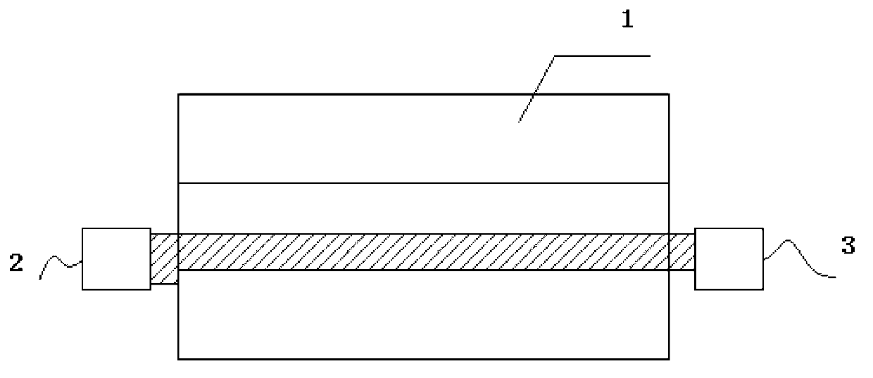
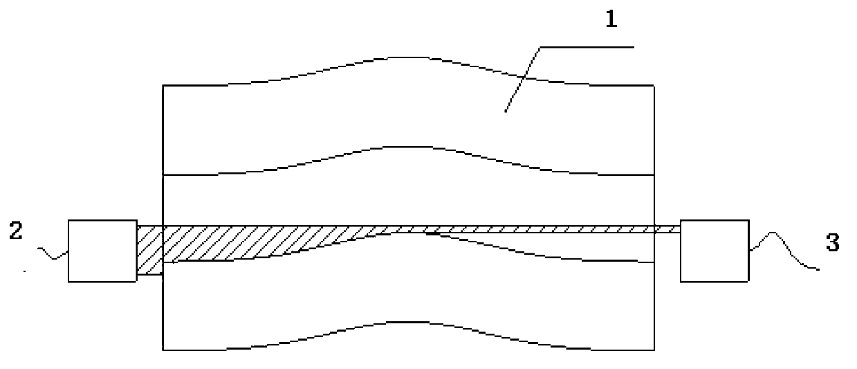
[0042] like figure 1 As shown, a cable force measuring device includes a pin shaft 1 and an ear plate 5. An axial through hole is opened on the axial center axis of the pin shaft 1, and the optical measuring system is placed symmetrically at both ends of the axial through hole. At the transmitting end and the receiving end, the measurement plane of the optical measurement system is coplanar with the axial axis of the pin shaft and the direction of the load, and the lug plate is connected to the pin shaft with a limit device.
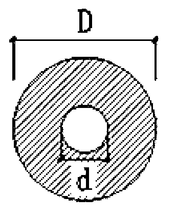
[0043] like image 3 As shown, the diameter d of the axial through hole is more than 10mm, and the area of the axial through hole accounts for ≤12% of the area of the pin shaft. The ratio of shaft section moment of inertia ≥ 97.5%.
[0044] The resolution of the optical measurement system is ≤0.01mm.
[0045] The optical measurement system includes a laser emitting end 2 and a laser receiving end 3 .
[0046] like Figure 4 (a) As shown in (b), ...
Embodiment 2
[0057] 1. Calibration of standard test pieces in factory environment;
[0058] A method for measuring cable force, comprising the steps of:
[0059] S1 performs pretreatment on the pin shaft 1 and the lug plate 5;
[0060] There is an axial hole at the central axis of the pin shaft, and a limit device is set at the lug plate to connect the pin shaft, so that the plane of the laser light curtain and the pulling force direction of the cable are coplanar, and the limit device is not limited. Setting the limit device to connect the pin shaft is specifically as follows: set two pins at the pin shaft, and two small limit slots are opened on the lug plate, and the pins match the small limit slots. In the actual structural stress, The existing pin shafts can rotate freely relative to the lug plate. Since the measuring instruments are all installed on the pin shafts, when the pin shafts rotate, the plane of the laser light curtain and the force direction of the cables are not on the s...
PUM
| Property | Measurement | Unit |
|---|---|---|
| yield strength | aaaaa | aaaaa |
Abstract
Description
Claims
Application Information
 - R&D
- Intellectual Property
- Life Sciences
- Materials
- Tech Scout
- Unparalleled Data Quality
- Higher Quality Content
- 60% Fewer Hallucinations
Browse by: Latest US Patents, China's latest patents, Technical Efficacy Thesaurus, Application Domain, Technology Topic, Popular Technical Reports.
© 2025 PatSnap. All rights reserved.Legal|Privacy policy|Modern Slavery Act Transparency Statement|Sitemap|About US| Contact US: help@patsnap.com


