Enclosure pipeline-type stator evaporating and cooling device

An evaporative cooling, pipeline technology, applied in the direction of cooling/ventilation device, electromechanical device, casing/housing/support, etc. The effect of reducing the number of joints, good cooling effect, and high cooling efficiency

Inactive Publication Date: 2013-09-04
INST OF ELECTRICAL ENG CHINESE ACAD OF SCI
View PDF7 Cites 12 Cited by
  • Summary
  • Abstract
  • Description
  • Claims
  • Application Information

AI Technical Summary

Problems solved by technology

But the disadvantages are: the cooling effect is greatly affected by the external environment, the cooling efficiency is not high, and the unclosed cooling space is easily eroded by wind, sand, moisture, etc.; and the temperature distribution of the cooled object is uneven, and hot spots may appear. Thus destroying the winding insulation and affecting the service life of the motor
However, the above traditional pipeline internal cooling evaporative cooling device mainly has two shortcomings: one is that the hollow wire is arranged in the stator slot, which will inevitably occupy the space in the slot and reduce the slot full rate, especially for motors with a large number of slots , which will increase the volume and materials of the motor; on the other hand, one or more hollow wires need to be installed in each tank, and each hollow wire needs to be connected with the gas collecting pipe and the liquid collecting pipe through the electro-hydraulic separati

Method used


Image

  • Enclosure pipeline-type stator evaporating and cooling device
  • Enclosure pipeline-type stator evaporating and cooling device
  • Enclosure pipeline-type stator evaporating and cooling device

Examples


Embodiment Construction

[0023] The content of the present invention will be further described below in conjunction with the accompanying drawings and specific embodiments.

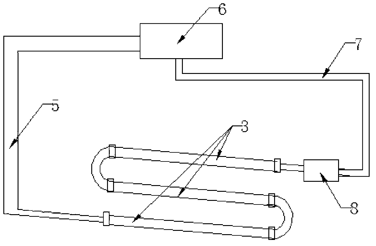
[0024] The stator evaporative cooling device of the present invention has two implementation modes of self-circulation and forced circulation.

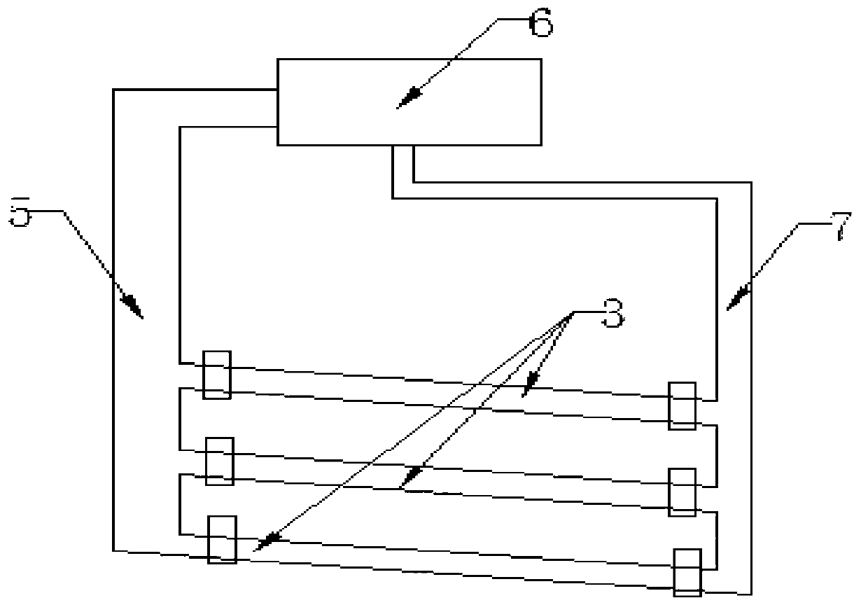
[0025] figure 1 Shown is an example of self-circulation. The self-circulating stator evaporative cooling device of the present invention includes a cooling pipeline 3 , an air collecting pipe 5 , a condenser 6 and a liquid return pipe 7 . In order to achieve self-circulation, the condenser 6 is installed at a certain height above the motor; one end of the air collecting pipe 5 is connected to the outlet of the cooling pipeline 3, and the other end of the air collecting pipe 5 communicates with the condenser 6; one end of the liquid return pipe 7 is connected to the condenser 6. The other end of the liquid return pipe 7 is connected to the inlet of the cooling pipeline 3 . The inside o...


PUM


Abstract

The invention discloses an enclosure pipeline-type stator evaporating and cooling device, which comprises a cooling pipeline (3), a gas collecting tube (5), a condenser (6) and a liquid returning tube (7), wherein the condenser (6) is installed above a motor; one end of the gas collecting tube (5) is connected with the outlet of the cooing pipeline (3); the other end of the gas collecting tube (5) is communicated with the condenser (6); one end of the liquid returning tube (7) is connected with the condenser (6); the other end of the liquid returning tube (7) is connected with the inlet of the cooing pipeline (3); secondary cooing medium is introduced into the condenser (6); the above components form a self-circulation evaporating and cooling loop; a pump (8) is connected between the liquid returning tube (7) and the cooling pipeline (3) to form a forced circulating evaporating and cooling loop; the cooling pipeline (3) is formed by connecting a plurality of cooling pipelines in parallel or series; the cooling pipeline (3) is arranged on the inner wall of a motor enclosure (4) or the outer wall of the motor enclosure (4); the cooling pipeline (3) can be arranged on the rectangular notch of the outer circumstance of a stator (1); and the outer cross section of the cooling pipeline (3) on the notch is rectangular.

Description

technical field [0001] The invention relates to a stator evaporative cooling device. Background technique [0002] With the increase of motor capacity, the calorific value increases, and the heat dissipation capacity of the motor directly affects the performance and life of the motor, which puts forward higher requirements for the cooling system of the motor. At present, air cooling and liquid cooling are generally used to cool the motor stator core, winding coil and its fixed parts. Air cooling uses air flow to remove the heat generated by the loss of various components. Its advantages are: relatively simple structure, convenient and feasible, low initial investment and operating costs. But the disadvantages are: the cooling effect is greatly affected by the external environment, the cooling efficiency is not high, and the unclosed cooling space is easily eroded by wind, sand, moisture, etc.; and the temperature distribution of the cooled object is uneven, and hot spots m...

Claims


Application Information

Patent Timeline
IPC IPC(8): H02K9/20H02K5/20
Inventor 闫静郭卉顾国彪田新东宋福川袁佳毅
Owner INST OF ELECTRICAL ENG CHINESE ACAD OF SCI
Why Eureka
Try Eureka