Method for producing a brake lining carrier

A technology of brake linings and disc brakes, which is applied in the direction of brake components, friction linings, brake types, etc., can solve problems such as breakage of brake lining brackets, and achieve the effect of improving retention

Active Publication Date: 2013-09-04
迅捷系统公司
View PDF11 Cites 2 Cited by
  • Summary
  • Abstract
  • Description
  • Claims
  • Application Information

AI Technical Summary

Problems solved by technology

As a result, breakage of the brake lining

Method used


Image

  • Method for producing a brake lining carrier
  • Method for producing a brake lining carrier
  • Method for producing a brake lining carrier

Examples


Embodiment Construction

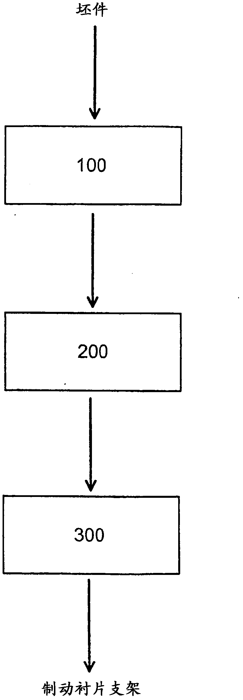
[0038] according to figure 1 In the embodiment shown in , firstly a blank made of steel plate is provided as workpiece. In method step 100, the blank is conveyed to the machine for use in the horizontal working direction ( Figure 8 In the plane of the drawing) a workstation 30 for upsetting an edge section of a blank, more precisely for producing a material thickening of predetermined dimensions on the edge side. Figure 8 The arrangement of the workstations 30 on the lower processing part 20 of the processing device is shown schematically. Sections of the edge of the workpiece are forged by means of the workstation 30 in a direction transverse to, in particular perpendicular to, the drawing direction (perpendicular to the plane of the drawing). At the same time, the workpiece is perforated at a predetermined position and is provided with an edge-side recess to be arranged at a predetermined position for arranging a wear indicator ( Figure 8 not shown).

[0039] Four rec...


PUM


Abstract

The invention relates to a method for producing a brake lining carrier (1), in particular for a disc brake of a vehicle, wherein a band-shaped or plate-shaped workpiece is deep-drawn in a direction perpendicular to the plane of the workpiece. In order to create at least one material thickening at the edge, the workpiece is upset transversely, in particular perpendicularly, to the deep drawing direction, wherein the thickness (B) of the material thickening thus generated is greater than the thickness of the starting material (A).

Description

technical field [0001] The invention relates to a method for producing a brake lining carrier, in particular for a disc brake of a motor vehicle, wherein a strip-shaped or plate-shaped workpiece is deep-drawn in a direction perpendicular to the workpiece plane . Furthermore, the invention relates to a brake lining carrier and a processing device, in particular a forming tool, for carrying out the method. Background technique [0002] Brake lining carriers are known, for example, in connection with disc brakes of motor vehicles and form brake pads together with the brake linings arranged thereon. The brake pads are connectable to the brake caliper via the brake lining carrier. The brake caliper has at least one piston by means of which the brake pad is movable towards the brake disc of the disc brake. During the braking process, the brake lining carrier is used to transmit lateral forces from the brake lining to the brake caliper, which are generated by the contact between...

Claims


Application Information

Patent Timeline
IPC IPC(8): F16D65/092F16D69/04
CPCF16D65/092F16D69/0408F16D2069/0491F16D2250/0023
Inventor T·扬策尔
Owner 迅捷系统公司
Why Eureka
Try Eureka