Carbon dioxide separating and collecting system and method of operating same

A technology for separation and recovery of carbon dioxide, applied in separation methods, chemical instruments and methods, and separation of dispersed particles, which can solve the problems of reduced energy consumption and smaller effects of regeneration towers

Inactive Publication Date: 2013-09-11
KK TOSHIBA
View PDF7 Cites 3 Cited by
  • Summary
  • Abstract
  • Description
  • Claims
  • Application Information

AI Technical Summary

Problems solved by technology

As a result, further upsizing of the regenerative heat exchanger is required
On the other hand, if the low-temperature absorption liquid is supplied to the regeneration tower in the state where the above-mentioned temperature difference is large, the effect of reducing the energy consumption of the regeneration tower by the regenerative heat exchanger becomes small.

Method used


Image

  • Carbon dioxide separating and collecting system and method of operating same
  • Carbon dioxide separating and collecting system and method of operating same
  • Carbon dioxide separating and collecting system and method of operating same

Examples


no. 1 Embodiment approach )

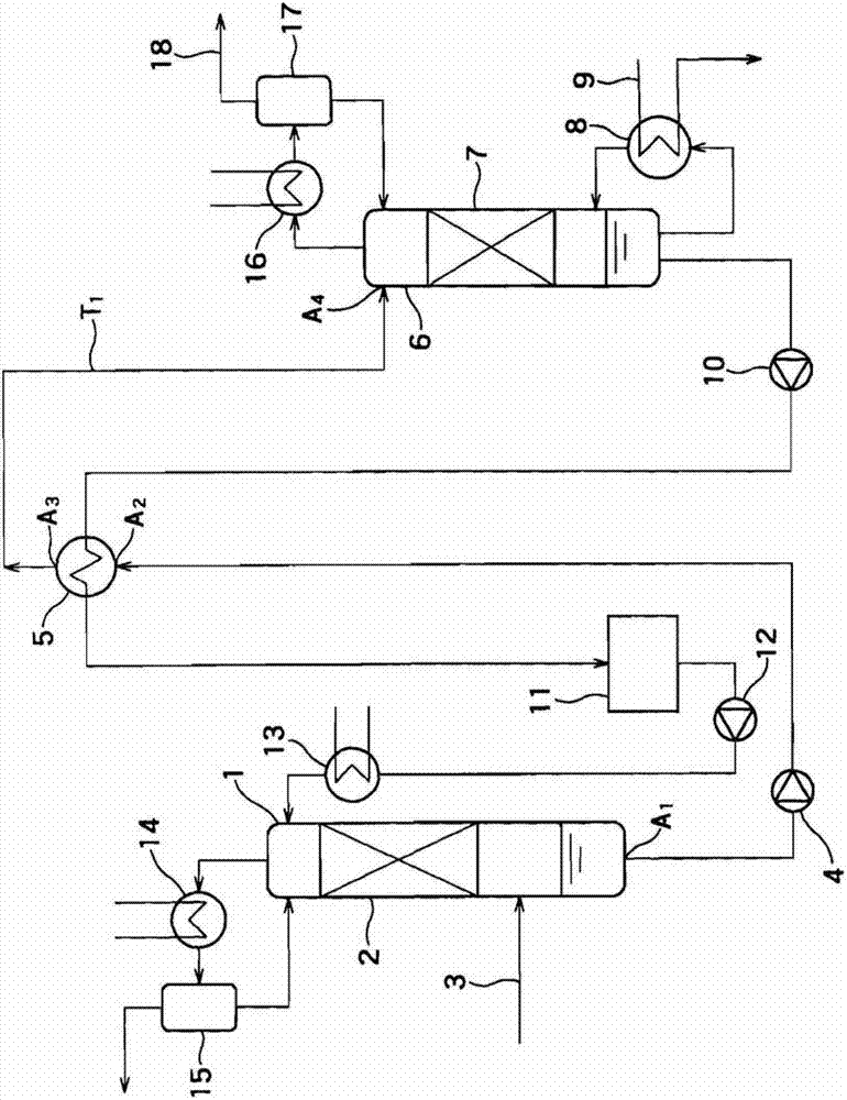
[0021] figure 1 It is a schematic diagram showing the structure of the carbon dioxide separation and recovery system of the first embodiment.

[0022] figure 1 The carbon dioxide separation and recovery system consists of absorption tower 1, absorption tower packing layer 2, combustion exhaust gas supply port 3, rich liquid transfer pump 4, regeneration heat exchanger 5, regeneration tower 6, regeneration tower packing layer 7, regeneration tower reboiler 8. Reboiler heating medium supply port 9, lean liquid transfer pump 10, lean liquid tank 11, lean liquid return pump 12, lean liquid cooler 13, absorption tower reflux cooler 14, absorption tower gas-liquid separator 15, Regeneration tower reflux cooler 16, gas-liquid separator 17 for regeneration tower, and recovery of CO 2 Drain line 18.

[0023] Combustion exhaust gas from a thermal power plant or the like is introduced into the lower part of the absorption tower 1 through the combustion exhaust gas supply port 3 . The...

no. 2 Embodiment approach )

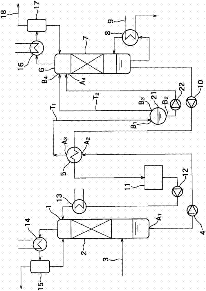
[0064] image 3 It is a schematic diagram showing the structure of the carbon dioxide separation and recovery system of the second embodiment.

[0065] image 3 The carbon dioxide separation and recovery system in addition to figure 1 In addition to the shown components, a first gas-liquid separator 21 and a first semi-lean liquid transfer pump 22 are further provided.

[0066] The first gas-liquid separator 21 is provided between the regeneration heat exchanger 5 and the regeneration tower 6, and separates the rich liquid discharged from the regeneration heat exchanger 5 into gas and liquid. Label B 1 , B 2 , B 3 A rich liquid supply port, a liquid discharge port, and a gas discharge port of the first gas-liquid separator 21 are respectively shown. from outlet B 2 , B 3 The discharged liquid and gas are respectively supplied from the supply port A 4 , B 4 It is supplied to the regeneration tower 6. In addition, this liquid (semi-poor liquid) is transferred to the r...

no. 3 Embodiment approach )

[0079] Figure 4 It is a schematic diagram showing the structure of the carbon dioxide separation and recovery system of the third embodiment.

[0080] Figure 4 The carbon dioxide separation and recovery system in addition to figure 1 In addition to the components shown, it also has a flow splitter 31, and CO 2 Ejector 32.

[0081] The splitter 31 is provided between the absorption tower 1 and the regenerative heat exchanger 5, and separates the rich liquid flowing therebetween into first and second rich liquids. And, the first rich liquid is supplied to the regenerative heat exchanger 5, and the second rich liquid is supplied to the CO 2 Ejector 32 supplies. The distribution ratio of the first and second rich solutions is, for example, 85 to 90% versus 10 to 15%.

[0082] CO 2 The discharger 32 is provided between the splitter 31 and the regeneration tower 6, and heats the second rich liquid with the heat of the exhaust gas discharged from the regeneration tower 6 to ...


PUM


Abstract

The invention provides a carbon dioxide separating and collecting system and the method of operating the same which can increase the recovered heat quantity in the regenerative heat exchanger. According to one embodiment, a carbon dioxide separating and collecting system includes an absorbing tower to cause an absorbing liquid to absorb carbon dioxide, and discharge a rich liquid which is the absorbing liquid which has absorbed the carbon dioxide. The system includes a regenerating tower to cause the absorbing liquid to release the carbon dioxide, and discharge a lean liquid which is the absorbing liquid having a dissolved carbon dioxide concentration lower than a dissolved carbon dioxide concentration of the rich liquid. The system further includes a regenerative heat exchanger configured to heat the rich liquid flowing between the absorbing tower and the regenerating tower by using heat of the lean liquid flowing between the regenerating tower and the absorbing tower. A discharge port of the rich liquid of the regenerative heat exchanger is disposed at a higher position than a supply port of the rich liquid of the regenerating tower so that the rich liquid discharged from the regenerative heat exchanger become a gas-liquid two-phase flow.

Description

technical field [0001] The invention relates to a carbon dioxide separation and recovery system and an operation method thereof. Background technique [0002] In recent years, due to the carbon dioxide (CO 2 ) The problem of global warming brought about by the greenhouse effect becomes larger. Against such a background, a method of separating and recovering carbon dioxide in the combustion exhaust gas by bringing the combustion exhaust gas into contact with an amine-based absorbent for thermal power plants that use a large amount of fossil fuels, and recovering the recovered carbon dioxide Methods of storage without release to the atmosphere are being actively studied. [0003] As an example of a method for separating and recovering carbon dioxide using such an absorbing liquid, there may be mentioned a process including contacting combustion exhaust gas with an absorbing liquid in an absorption tower, making the absorbing liquid absorb carbon dioxide in the combustion exh...

Claims


Application Information

Patent Timeline
Patent Type & Authority Applications(China)
IPC IPC(8): B01D53/14C01B32/50
CPCB01D53/1425B01D53/1475Y02C20/40
Inventor 大桥幸夫小川斗北村英夫
Owner KK TOSHIBA
Why Eureka
Try Eureka