U-shaped radiant tube

A radiant tube and U-shaped technology, which is applied in the field of U-shaped radiant tubes, can solve the problems of low heat transfer efficiency and uneven temperature, and achieve the effects of high heat transfer efficiency, high preheating temperature and long service life

Inactive Publication Date: 2017-05-31
CERI PHOENIX INDAL FURNACE CO TD +2
View PDF4 Cites 1 Cited by
  • Summary
  • Abstract
  • Description
  • Claims
  • Application Information

AI Technical Summary

Problems solved by technology

[0004] The invention provides a U-shaped radiant tube to solve the problems of uneven temperature on both sides of the existing U-shaped radiant tube and low heat exchange efficiency

Method used


Image

  • U-shaped radiant tube
  • U-shaped radiant tube
  • U-shaped radiant tube

Examples


Embodiment Construction

[0033] In order to have a clearer understanding of the technical features, purposes and effects of the present invention, the present invention will now be described with reference to the accompanying drawings.

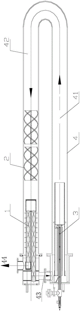
[0034] Such as figure 1 and figure 2 As shown, the present invention proposes a U-shaped radiant tube, the U-shaped radiant tube has a U-shaped flue gas channel arranged in the tube body 4 of the U-shaped radiant tube, and the flue gas channel is connected with the external smoke exhaust of the burner The system communicates, the U-shaped flue gas channel includes: the exhaust side channel 42 and the combustion side channel 41, and the U-shaped radiant tube includes:

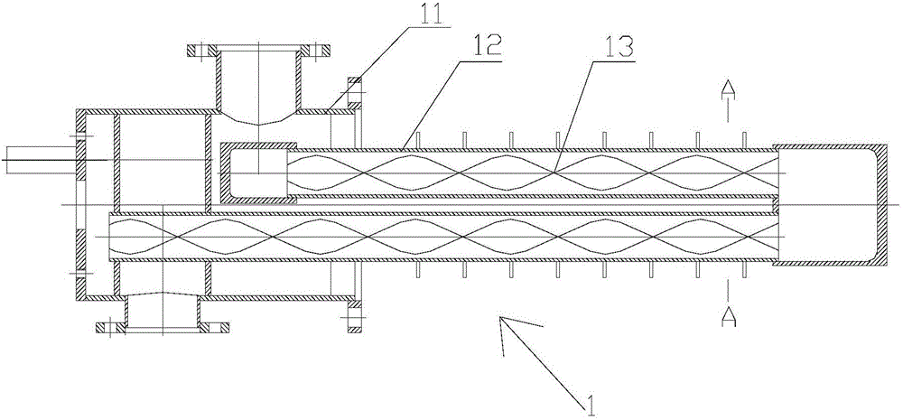
[0035] The heat exchanger 1, namely the burner heat exchanger, is arranged at the end of the smoke exhaust side channel 42 of the U-shaped radiant tube (located on the smoke exhaust side of the U-shaped radiant tube burner);

[0036] The burner nozzle 3 is arranged at the head end of the combustion s...


PUM


Abstract

The invention provides a U-shaped radiant tube. The U-shaped radiant tube is provided with a U-shaped flue gas duct. The U-shaped flue gas duct comprises a smoke exhaust side channel and a combustion side channel. The U-shaped radiant tube comprises a heat exchanger, a nozzle and a rotational flow device made of a non-metal material, wherein the heat exchanger is arranged at the tail end of the smoke exhaust side channel of the U-shaped radiant tube, the nozzle is arranged at the head end of the combustion side channel of the U-shaped radiant tube, and the rotational flow device made of the non-metal material is arranged in the smoke exhaust side channel of the U-shaped radiant tube and located between the heat exchanger and the nozzle. The heat exchanger comprises a pipe body and metal fins arranged in the pipe body. By the adoption of the U-shaped radiant tube, the production energy consumption can be lowered effectively, the capacity of the radiant tube can be improved effectively, and the U-shaped radiant tube is especially suitable for transformation with the requirement of lowering the energy consumption or the requirement of improving the heating capacity of the radiant tube.

Description

technical field [0001] The invention relates to the field of heat exchangers, in particular to a U-shaped radiant tube. Background technique [0002] The U-shaped radiant tube is an indirect heating device made of cast or welded heat-resistant steel pipes. The heating process is that the fuel is ejected from the nozzle of the burner, mixed with the combustion-supporting air and then burned, and the combustion product - high-temperature flue gas flows from the intake side of the radiant tube to the exhaust side and then discharged. With the flow of the flue gas in the radiant tube, the temperature of the combustion products gradually decreases with the heat dissipation of the radiant tube, so that there is a problem that the temperature of the side wall of the gas supply is high and the temperature of the side wall of the exhaust gas is low when it is used, resulting in the temperature difference between the two sides of the tube and the capacity of the radiant tube. Can't p...

Claims


Application Information

Patent Timeline
Patent Type & Authority Applications(China)
IPC IPC(8): F28D7/06F28F9/22
CPCF28D7/06F28F9/22F28F2009/222
Inventor 戴文文朱承业雷奇胡文超朱小辉江华
Owner CERI PHOENIX INDAL FURNACE CO TD
Why Eureka
Try Eureka