
Rapid measurement system and error compensation method for five-coordinate CNC machine tool swing angle

A technology of numerical control machine tools and compensation methods, which is applied in the direction of measuring/indicating equipment, metal processing machinery parts, other manufacturing equipment/tools, etc., can solve the problems of unable to realize automatic measurement, unable to realize compensation calculation, unable to meet measurement requirements, etc., to achieve Convenient and fast positioning accuracy, reducing equipment maintenance costs, and saving external employment costs

Active Publication Date: 2015-10-14
SHENYANG AIRCRAFT CORP
View PDF4 Cites 1 Cited by
  • Summary
  • Abstract
  • Description
  • Claims
  • Application Information

AI Technical Summary

Problems solved by technology

Laser interferometer can achieve relatively accurate measurement for straight line and small angle accuracy measurement, but for + / -15 degrees or even larger angle measurement, this method cannot meet the measurement requirements; other methods are mainly cumbersome to operate , completely manual programming and counting, unable to realize automatic measurement
Moreover, these methods are unable to carry out multi-point continuous measurement and the automatic compilation output of the measurement NC program, so they do not involve the calculation method of the continuous swing angle measurement program, and the calculation of the compensation value involved is also directly based on single-point measurement. The calculation method cannot realize continuous compensation calculation, so the measurement efficiency is low

Method used


Image

  • Rapid measurement system and error compensation method for five-coordinate CNC machine tool swing angle
  • Rapid measurement system and error compensation method for five-coordinate CNC machine tool swing angle
  • Rapid measurement system and error compensation method for five-coordinate CNC machine tool swing angle

Examples


Embodiment Construction

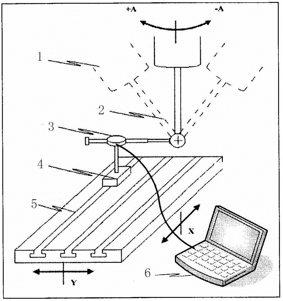
[0036] like figure 1 As shown, a measurement system for the positioning accuracy of the swing angle of a five-coordinate numerical control machine tool includes a ball mandrel 2, a digital display dial indicator 3 and a magnetic base 4, wherein the ball mandrel 2 is installed on the machine tool spindle 1, The digital display dial indicator 3 is installed on the magnetic base 4, and the magnetic base 4 is fixed on the machine tool workbench 5. The digital display dial indicator 3 is located at a positive position perpendicular to the machine tool spindle 1, and the digital display dial indicator 3 The measuring head of the machine tool is attached to the spindle 1 of the machine tool, and the digital display dial gauge 3 is connected to the computer terminal 6 .

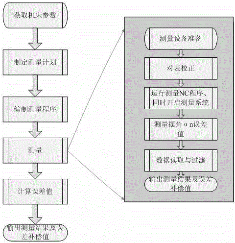
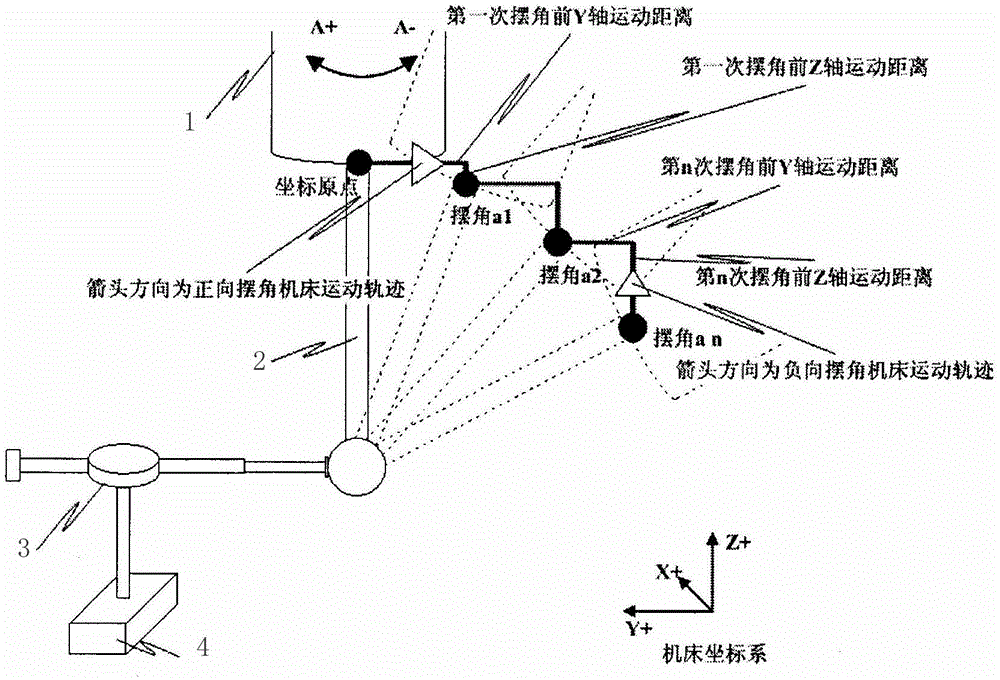
[0037] like figure 2 As shown, the following uses a MAG five-coordinate machining center to measure the A-axis as an example to specifically illustrate a calculation and compensation method for the measurement err...


PUM


Abstract

The invention provides a system for measuring positioning accuracy of a pendulum angle used by a five-axis numerical control machine tool. The system comprises a ball hear core rod, a digital display dial indicator and a magnetic force base, wherein the ball hear core rod is installed on a main shaft of the machine tool, the digital display dial indicator is installed on the magnetic force base which is fixed on a working table of the machine tool, the digital display dial indicator is located at the forward position which is perpendicular to the main shaft of the machine tool, a measurement head of the digital display dial indicator is tightly attached to the main shaft of the machine tool, and the digital display dial indicator is connected to a computer terminal. Through cooperation of the system and a method for computing and compensating measuring errors, automated measurement of positioning accuracy of an A axis and a B axis of the five-axis numerical control machine tool within the pendulum angle of + / -90 degrees and continuous computing of a multiple point compensation value can be achieved, and measurement accuracy and measurement efficiency are high.

Description

technical field [0001] The invention relates to a measurement system for the positioning accuracy of the swing angle of a five-coordinate numerical control machine tool and a compensation method for measurement errors, belonging to the technical field of mechanical processing. Background technique [0002] At present, in China, there is no relatively mature and highly automated measurement system for the measurement and error compensation of the positioning accuracy of the five-coordinate machining center. Common methods include 360-tooth precision indexing standard turntable, angle polyhedron, laser interferometer or direct dial gauge measurement, etc. Laser interferometer can achieve relatively accurate measurement for straight line and small angle accuracy measurement, but for + / -15 degrees or even larger angle measurement, this method cannot meet the measurement requirements; other methods are mainly cumbersome to operate , completely manual programming and counting, au...

Claims


Application Information

Patent Timeline
Patent Type & Authority Patents(China)
IPC IPC(8): B23Q17/00B23Q23/00
Inventor 房志亮方柏鑫金星邸楠
Owner SHENYANG AIRCRAFT CORP
Learn More