High-capacity microwave photocatalytic waste water degradation device for restraining reverse crossflow of ozone

A wastewater degradation device and high-capacity technology, applied in chemical instruments and methods, water/sewage multi-stage treatment, water/sludge/sewage treatment, etc. Tightness, no vacuum tightness, etc.

Inactive Publication Date: 2013-09-11
李榕生
View PDF4 Cites 0 Cited by
  • Summary
  • Abstract
  • Description
  • Claims
  • Application Information

AI Technical Summary

Problems solved by technology

[0048] Based on the structure of the CN102260003A scheme, during its operation, the air pumped into the quartz tube cavity will be irradiated by ultraviolet rays, part of which will be converted into ozone, and most of the ozone-containing air formed in this way will be sent to the micropore aeration by pressure However, we know that the structure of the magnetron itself is not vacuum-tight, and the connection between the waveguide and the magnetron is generally not vacuum-tight, so all the relatively positive pressure A small part of the above-mentioned ozone-containing air will inevitably flow into the structural area where the magnetron is located, and the structural component materials of the magnetron, including its shell material, generally do not have the ability to resist ozone corrosion. Then, such a In the future, the ozone-containing air that enters the magnetron structure area in the reverse direction will inevitably form a corrosion effect on the magnetron components. The power of this corrosion effect may be difficult to detect in a short period of time on the laboratory scale. However, it will definitely appear after a little longer time. , the problem of reverse flow of ozone-containing air and corrosion of magnetron components cannot be avoided, this is the fifteenth problem

Method used


Image

  • High-capacity microwave photocatalytic waste water degradation device for restraining reverse crossflow of ozone
  • High-capacity microwave photocatalytic waste water degradation device for restraining reverse crossflow of ozone

Examples


Embodiment Construction

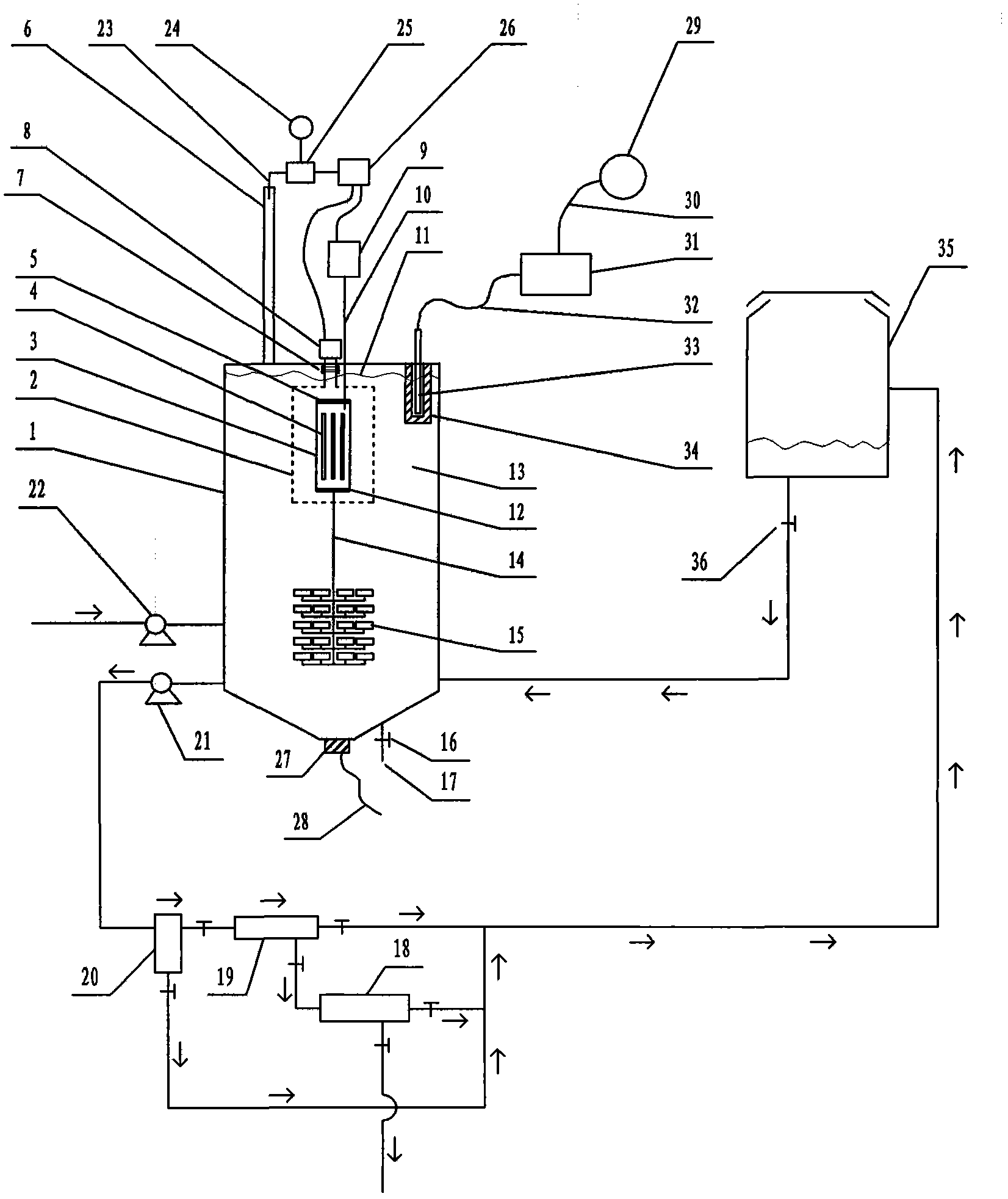
[0129] exist figure 1In the example of the present case shown, the structure of the device in this example includes a reactor 1, which is a hollow container. Prismatic, spherical or ellipsoidal, many microporous aeration heads 15 are installed in the lower area of ​​the inner chamber of the reactor 1, and the mark 15 only indicates the individual microporous aeration heads, and 15 only indicates the micropores The individual form of the aeration head, and, quartz tube 3, this quartz tube 3 is set up in the inner cavity position of described reactor, and the two ends of this quartz tube 3 are equipped with sealing cap 5,12, are respectively positioned at quartz tube 3 Both ends are provided with a ventilation interface, and the electrodeless ultraviolet lamp 4, the electrodeless ultraviolet lamp 4 is rod-shaped, ring-shaped, spherical, starfish-shaped or sea urchin-shaped, and the quantity of the electrodeless ultraviolet lamp 4 At least one, the number of at least one electro...


PUM


Abstract

The invention relates to a high-capacity microwave photocatalytic waste water degradation device for restraining the reverse crossflow of ozone, belonging to the technical field of waste water treatment. Problems such as microwave energy waste, lower single-tank waste water treatment capacity, difficulty in distinguishing a degradation endpoint moment, incapability of powerfully dissipating catalyst clusters in situ and detecting catalyst agglomeration in time and magnetron corrosion caused by reverse crossflow of secondary ozone exist in the traditional relevant technologies, and the scheme aims to solve the series of problems. The high-capacity microwave photocatalytic waste water degradation device has the structural advantages that a microwave irradiation airspace is limited, and the capacity of a reactor is allowed to be expanded greatly; a catalyst is intercepted stage by stage by using an external multi-stage cascade backwash filter; the catalyst clusters are dissipated by using low-frequency ultrasonic waves, and meanwhile, a quartz tube is cleaned; relevant power sources can be automatically and immediately turned off when a degradation end point is reached; the catalyst agglomeration trend can be warned; and a waveguide tube is separated by using a wave-transparent airtight partition plate to block the reverse crossflow ozone and strengthen the anticorrosion maintenance for a magnetron.

Description

technical field [0001] The invention relates to a large-capacity microwave photocatalytic waste water degradation device for suppressing reverse channeling of ozone, and belongs to the technical field of CO2F waste water treatment. Background technique [0002] Microwave photocatalytic degradation treatment technology, as an effective harmless treatment technology for industrial wastewater containing organic pollutants, has attracted much attention in recent years. [0003] Regarding the microwave photocatalytic degradation technology, as an example, refer to the Chinese patent application with publication number CN102260003A. [0004] The Chinese patent application with the publication number CN102260003A uses microwaves as the excitation source to excite the electrodeless ultraviolet lamp to emit ultraviolet rays, and irradiates the suspension mixed with photocatalyst titanium dioxide inside the liquid. The electrodeless ultraviolet lamp is shrouded and protected by a quar...

Claims


Application Information

Patent Timeline
IPC IPC(8): C02F9/08
Inventor 李榕生
Owner 李榕生
Why Eureka
Try Eureka