Tube-shell type solid-solid heat exchanger

A heat exchanger, shell-and-tube technology, which is applied in the field of shell-and-tube solid-solid heat exchangers, can solve the problems that no feasible method has been found, the limitation of solvent-oil ratio, etc., and achieve the goal of increasing the liquid yield of the device and increasing the solvent-oil ratio Effect

Inactive Publication Date: 2015-07-15
CHINA UNIV OF PETROLEUM (BEIJING)
View PDF5 Cites 2 Cited by
  • Summary
  • Abstract
  • Description
  • Claims
  • Application Information

AI Technical Summary

Problems solved by technology

[0005] Although this method can increase the ratio of agent to oil to a certain extent, the problem with this method is that under the conditions that the carbon content of the catalyst is roughly constant, the regeneration temperature is constant, and the heat generated by the regenerator is constant, With the increase of the agent-oil ratio, the heat taken by the external heat extractor gradually increases. This part of the heat is used to generate water vapor and merged into the steam pipe network, and will not return to the regeneration system. The increase of the agent-oil ratio is limited to a certain extent.
In the process of catalytic cracking, thermal stripping of the raw agent can produce good results. At present, a lot of research has been carried out, but no feasible method has been found. The shell-and-tube solid-solid heat exchanger proposed by the present invention solves this problem

Method used


Image

  • Tube-shell type solid-solid heat exchanger

Examples


Embodiment Construction

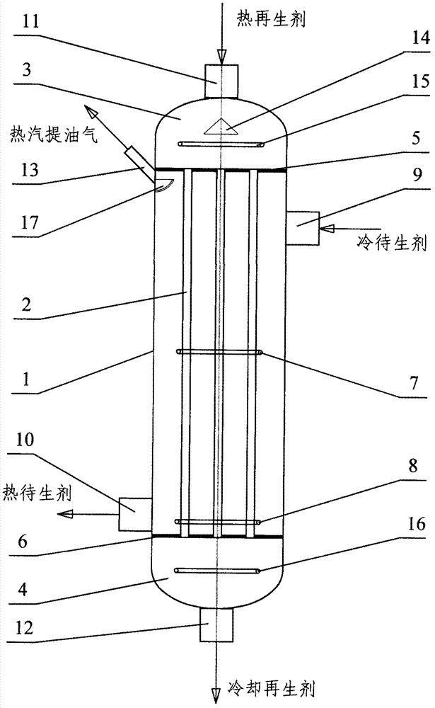
[0027] figure 1 It shows a shell-and-tube solid-solid heat exchanger, which consists of a shell (1), a heat exchange tube (2), an upper head (3), a lower head (4), an upper tube sheet (5), a lower tube sheet (6), fluidization air distributor in the middle of the shell side (7), fluidization air distributor in the lower part of the shell side (8), inlet of cold standby agent (9), outlet of hot standby agent (10), inlet of hot regeneration agent (11), cooling regeneration agent outlet (12), hot stripping oil gas outlet (13), catalyst distribution plate in the upper part of the tube pass (14), fluidization air distributor in the upper part of the tube pass (15), fluidization air distribution in the lower part of the tube pass device (16), arc-shaped baffle (17); the shell side is composed of the shell (1), heat exchange tube (2), upper tube sheet (5), and lower tube sheet (6). The head (3), the lower head (4) and the internal flow space of the heat exchange tube (2) form the tub...


PUM


Abstract

The invention relates to a tube-shell type solid-solid heat exchanger without blending between cold and hot solid particles for heat exchange, inner spaces of an upper sealing head (3) and a lower sealing head (4) and the inner space of a heat exchange tube (2) form a tube pass, a space defined by a shell (1), an upper tube plate (5), a lower tube plate (6) and a heat exchange tube (2) forms a shell pass, fluidizers are respectively arranged in the tube pass and the shell pass, the cold and hot solid particles are fluidified and flow in the shell pass and the tube pass respectively, and heat exchange is realized between the cold and hot solid particles by virtue of the heat exchange tube (2). By adopting the tube-shell type solid-solid heat exchanger, heat exchange can be carried out between a thermal regeneration agent and a cold spent agent of a catalytic cracking unit, thus stable operation with high agent-oil ratio is realized, thermal balance of the whole device is maintained, and liquid yield of the tube-shell type solid-solid heat exchanger is increased; and thermal steam stripping on the spent agent can be realized, and benefit of the catalytic cracking unit is increased. The tube-shell type solid-solid heat exchanger provided by the invention can be applied to all the catalytic cracking units and other devices requiring heat exchange between the cold and hot solid particles.

Description

Technical field [0001] The invention relates to a shell-and-tube solid-solid heat exchanger for heat exchange without mixing between cold and hot solid particles. Fluidized flow in the stroke, heat exchange between cold and hot solid particles through the heat exchange surface. Through this device, it is possible to realize the operation of a large fuel-to-oil ratio on the catalytic cracking unit and maintain the heat balance of the whole system, so as to realize the energy-saving and stable operation of a large fuel-to-oil ratio in the catalytic cracking process and increase the liquid yield of the device. Background technique [0002] In the patent No. 201010603785.3, a process method for realizing a stable and large fuel-to-oil ratio operation in a catalytic cracking process is proposed. The invention relates to a shell-and-tube solid-solid heat exchanger for heat exchange between cold and hot catalysts, which can provide assistance for realizing the above-mentioned proc...

Claims


Application Information

Patent Timeline
Patent Type & Authority Patents(China)
IPC IPC(8): C10G11/18
Inventor 王娟郝希仁毛羽王江云
Owner CHINA UNIV OF PETROLEUM (BEIJING)
Why Eureka
Try Eureka